I got this older 2950 out of the cabinet and when first fired up, the receive would cut in and out, I think it had low power but can't remember...been playing with this for a few days.
I replaced all the electrolytic caps, and as stated in another post, I found about 4 totally bad caps, and a few over and below ratings. That seemed to cure the issues with the in and out receive. So on to the next step with the PLL alignment. All went as it should with all the voltages set,coils that needed to be adjusted with the scope all went well. AM alignment spot on, USB spot on. Now comes the problem with the LSB portion. Best I could get was 10.6954, and it should be 10.6975. Thinking maybe the L28 coil, a 12016, I replaced it with a new one I had. Same issue although I think it may have settled in to the 10.6975 for a second...maybe. Like I said I've been working on this for a few days and my mind is in a jumble.
Went through all the steps again today hoping for some over night divine intervention but alas, same results.
I've included some pictures of the coil(s). The first on the left is the original with the group picture and the next to the right is out of the same bog of new replacements. The 3rd and 4th in line were in the bin with the others, at least one came from a 959 if i remember correct.
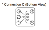
I was wondering if anyone could help me out with this, I would like to try and check the inductance of the coil but am not sure what pins to check.
The first 2 pics are of the original I pulled with part number and pins.


On the above pic, the first one is the original, the second one is identical to the replacement I used, and the other 2 are what was in my bin.
I think these would all be the same by the first 5 numbers being the same. The 2 on the right end have been used as there is some solder residue still on them. I don't usually throw stuff away until I can check them, and I don't know where to take the readings from these unfortunately.
Thanks for any and all help.
I replaced all the electrolytic caps, and as stated in another post, I found about 4 totally bad caps, and a few over and below ratings. That seemed to cure the issues with the in and out receive. So on to the next step with the PLL alignment. All went as it should with all the voltages set,coils that needed to be adjusted with the scope all went well. AM alignment spot on, USB spot on. Now comes the problem with the LSB portion. Best I could get was 10.6954, and it should be 10.6975. Thinking maybe the L28 coil, a 12016, I replaced it with a new one I had. Same issue although I think it may have settled in to the 10.6975 for a second...maybe. Like I said I've been working on this for a few days and my mind is in a jumble.
Went through all the steps again today hoping for some over night divine intervention but alas, same results.
I've included some pictures of the coil(s). The first on the left is the original with the group picture and the next to the right is out of the same bog of new replacements. The 3rd and 4th in line were in the bin with the others, at least one came from a 959 if i remember correct.
I was wondering if anyone could help me out with this, I would like to try and check the inductance of the coil but am not sure what pins to check.
The first 2 pics are of the original I pulled with part number and pins.
On the above pic, the first one is the original, the second one is identical to the replacement I used, and the other 2 are what was in my bin.
I think these would all be the same by the first 5 numbers being the same. The 2 on the right end have been used as there is some solder residue still on them. I don't usually throw stuff away until I can check them, and I don't know where to take the readings from these unfortunately.
Thanks for any and all help.