• You can now help support WorldwideDX when you shop on Amazon at no additional cost to you! Simply follow this Shop on Amazon link first and a portion of any purchase is sent to WorldwideDX to help with site costs.

Radials? and the end fed 1/2 wave (EFHW)

Which works best for the A99

  • 72" horizontal radials?

    Votes: 0 0.0%
  • No radials?

    Votes: 0 0.0%
  • Another configuration like Bob85's model posted?

    Votes: 0 0.0%

  • Total voters
    11
LOL, no that's not what I meant, and I'm not quite sure what you're asking.
What do you get when you run the A99 free space with a 26" length of coax underneath straight down to a choke, or just a 26" radial going straight down as if the A99 was mounted on a fiberglass mast and there was a choke wrapped in the coax 26" below the connector?
 
http://www.worldwidedx.com/cb-antennas/71031-half-wave-antennas-not-needing-ground-elements.html

another thread on ground elements on 1/2 waves .

*******************************************

"BM, in my opinion there is a big difference in how a 5/8 wave radiator is affected by radials and a 1/2 wave. The same applies to a 1/4 wave, but it needs radials even more so. Since Imax is a 5/8 wave, one might ask how it performs without radials? If you doubt this then you are Homer try your 5/8 wave ground planes without radials...and you'll see they don't work so good. The answer is in the matching device, just like Shockwave told us some time back."

i agree with you OGP . but the poll question is "Which works best for the A99" not what will work . i think it's more than obvious that the A99 does a excellent job for many people just as it is and some folks have better results with it than they do bigger 5/8's . some folks need the ground elements and a choke along with mast isolation to get good performance from them in their installations . i don't recall any comments from anyone saying that adding ground elements , choking and isolating ended up degrading the performance of there A99 . some have said it made no difference though .

IMO location (where it's at and whats around it) will dictate what a A99 (or any other) antenna will do . if i feel a antenna needs ground elements i'd add some that were resonate for the frequency/band it will be used on . just my thoughts ............
Very fair and sensible comment booty.
 
It would be interesting to know where the advantage is most apparant on a A99 as to where you mount the quarter wave ground planes. Do you go for the proximity to the radiator by mounting it underneath the tuning rings or do you mount it at the base of the mounting section near the SO239?
The A99 is difficult because of the length of coax inside and as mentioned before this will increase your electrical length of your GP kit before you even attach it. It would be interesting to know if the electrical length or proximity to the driven element is the most important. It may benefit owners of the A99 to scrap the existing SO239 socket and solder their coax direct to the tuning section. While your at it, solder a jumper from the outer shield of that connection to the very top of the mounting tube. That would make it easier all round but would mean a total stripdown.
 
sweet :D my sensible comment quota for the year has been filled ;)

Not fair BM.

My topic is about JJ's A99 idea, and you interjected an idea about a 5/8 wave antenna, and that is what I responded to, nothing more. That idea had nothing to do with the question I originally asked. I never mentioned that any of JJ's models would or would not work, I just asked what folks thought would work best among the options available.

Again, I was referring to your idea, because you were curious, and I told you why I disagreed that there was any radial similarities between a 1/4, 1/2, and 5/8 wave radiator and how they respond. Don't you get it?

Other ideas are fine, but we have to be on guard when mixing results from different ideas. The same applies to free space models and real Earth models, although all we see in JJ's A99 models is a difference in gain only, the trend lines, and the maximum current angles are pretty much the same.

It would be interesting to know where the advantage is most apparant on a A99 as to where you mount the quarter wave ground planes. Do you go for the proximity to the radiator by mounting it underneath the tuning rings or do you mount it at the base of the mounting section near the SO239?
The A99 is difficult because of the length of coax inside and as mentioned before this will increase your electrical length of your GP kit before you even attach it. It would be interesting to know if the electrical length or proximity to the driven element is the most important. It may benefit owners of the A99 to scrap the existing SO239 socket and solder their coax direct to the tuning section. While your at it, solder a jumper from the outer shield of that connection to the very top of the mounting tube. That would make it easier all round but would mean a total stripdown.

Nav, I've also wondered why the Imax GPK is at the bottom, and the A99 at the top of the mounts.

I don't know if this makes any difference in modeling the Imax, but IMO the radials just don't make much if any difference on the A99, modeling or real world testing. Reason being for me is: there is not much current flowing in that area of the antenna for an A99, and since there is more current flowing at the bottom of the Imax, maybe that is a good reason to put the radials at the bottom where there is some current. I've never tested a GPK on my Imax, but I find little to no affects...when installing a GPK on my A99.

The short piece of coax inside of the antenna should be almost totally transparent to the coaxial system, excepting for any affects from the connector, so making the coax to run all the way to the tuning coil would seem to me to be meaningless. It is similar to adding a short jumper.
 
Marconi wrote:
The short piece of coax inside of the antenna should be almost totally transparent to the coaxial system, excepting for any affects from the connector, so making the coax to run all the way to the tuning coil would seem to me to be meaningless. It is similar to adding a short jumper.
You've misunderstood me Marconi. Where the SO239 is located on the A99 is approx 10 or 12 inches from the tuning section (the length of the short piece of coax inside). This arrangement has a disadvantage over a standard half wave GP if you want to mount radials. The reason being: you would have to include the length of the mounting tube in your quarter wave electrical length to create your 108 inch radial otherwise you will have 132 inch radials.
To bypass this problem the easy solution would be to remove the SO239 completely and solder your coax direct to the feed point aswell as soldering a bridge from the top of the tube to your outer braid at the feed point. This would cut out the losses associated with feed point sockets, remove the mounting tube from the electrical length of your radials and ensure your radials are located where they should be electrically and in proximity to the radiator where they would be on a half wave GP.
 
Last edited:
Marconi wrote:

You've misunderstood me Marconi. Where the SO239 is located on the A99 is approx 10 or 12 inches from the tuning section (the length of the short piece of coax inside). This arrangement has a disadvantage over a standard half wave GP if you want to mount radials. The reason being: you would have to include the length of the mounting tube in your quarter wave electrical length to create your 108 inch radial otherwise you will have 132 inch radials.
To bypass this problem the easy solution would be to remove the SO239 completely and solder your coax direct to the feed point aswell as soldering a bridge from the top of the tube to your outer braid at the feed point. This would cut out the losses associated with feed point sockets, remove the mounting tube from the electrical length of your radials and ensure your radials are located where they should be electrically and in proximity to the radiator where they would be on a half wave GP.

I still don't understand.
 
Not fair BM.

My topic is about JJ's A99 idea, and you interjected an idea about a 5/8 wave antenna, and that is what I responded to, nothing more. That idea had nothing to do with the question I originally asked. I never mentioned that any of JJ's models would or would not work, I just asked what folks thought would work best among the options available.

Again, I was referring to your idea, because you were curious, and I told you why I disagreed that there was any radial similarities between a 1/4, 1/2, and 5/8 wave radiator and how they respond. Don't you get it?

Other ideas are fine, but we have to be on guard when mixing results from different ideas. The same applies to free space models and real Earth models, although all we see in JJ's A99 models is a difference in gain only, the trend lines, and the maximum current angles are pretty much the same.

sorry if i poo pooed on your thread . i just explained my reason for my choice in the options given . i just don't have much faith in Eznec5 or the other programs for simulating antenna performance simply because too often they don't jive with reports from real world users . but i'll just ask 2 simple questions ........

if a 1/2 wave doesn't benefit from having ground elements then why do folks sometimes get better performance with them ?

if someone is going to add ground elements to a antenna to get it's peak performance why would they want to use a length other than something that is resonate for the frequency/band its intended to be used on ?
 
This is what I mean. The current has to flow down the coax and up the mounting tube to get to the radials increasing the electrical length of any radial attached.
 

Attachments

  • A99.JPG
    A99.JPG
    21 KB · Views: 38
Last edited:
sorry if i poo pooed on your thread . i just explained my reason for my choice in the options given . i just don't have much faith in Eznec5 or the other programs for simulating antenna performance simply because too often they don't jive with reports from real world users . but i'll just ask 2 simple questions ........

if a 1/2 wave doesn't benefit from having ground elements then why do folks sometimes get better performance with them ?

if someone is going to add ground elements to a antenna to get it's peak performance why would they want to use a length other than something that is resonate for the frequency/band its intended to be used on ?
My opinion is more or less what you said earlier Booty - we all suffer different circumstances in our locations and our surroundings. For example, soil conductivity can change how one antenna behaves compared with the same antenna in another area. Attenuation from the local surroundings, the geological outlay such as hills, water, massive wide open spaces and so forth.
If I tested my antenna's in my own circumstances and claimed that is how they would behave in all other circumstances then I would regard myself as a fool because at the end of the day I have no idea how they behave in other places. To repeatedly suggest that something works or doesn't work because thats how it is for me is kinda being a lot on the narrow minded side. No one can claim to know if an antenna works better or not unless they have tested every kind of geological location the Earth has to offer. Its about what works best for you at the end of the day.

You know, I don't know if I agree because most of these verticals we're talking about are mounted at least a wave length above ground, some maybe even two wave lengths, and especially a metal 5/8 that carries the ground up with it in the form of 1/4 wave radials.
A dipole or yagi beam would certainly be affected by soil conductivity and height above ground would absolutely change the TOA on those. I just can't see the performance of a 1/4 wave radial type antenna changing much according to how far ground is below it.
I wonder if the modeling agrees and as it gets higher in the air does the ground conductivity have an ever lessening effect on it?
Marconi, what about comparing two models, one a normal 270" 5/8 with 1/4 wave radials and the other just a 5/8 wave without any radials, ignoring the swr and matching, I'm only interested in the pattern and TOA differences and at both 1/2 wave length and 2 wave lengths high above ground.
 
Height does effect TAO, no debate there.

Ground radials? The other half of the antenna per say.

Many verticals, ham antenna's included use the coax shield as the counterpoise, the coax radiates just as much if not more than the antenna itself. It is designed that way from the manufacture.

A no ground radial antenna is half the antenna.

Using ground radials on elevated verticals, in some situations help prevent CMC, Imax 2000 etc type antennas. Do they increase the performance? Maybe, by forcing the current onto the ground radials instead of the coax.

The current then becomes symmetrical per say and this results in a cleaner pattern of radiated signal.

Some will argue that their vertical with no ground plane out performs a vertical with a ground plane. I always ask "In what direction?". As a no ground plane vertical is left to radiate in a direction effected by the surrounding soil conditions, type of install and many other variables.

A vertical ground plane radiates poorly in all directions if properly installed.
But they do radiate.
 
sorry if i poo pooed on your thread . i just explained my reason for my choice in the options given . i just don't have much faith in Eznec5 or the other programs for simulating antenna performance simply because too often they don't jive with reports from real world users . but i'll just ask 2 simple questions ........

if a 1/2 wave doesn't benefit from having ground elements then why do folks sometimes get better performance with them ?

if someone is going to add ground elements to a antenna to get it's peak performance why would they want to use a length other than something that is resonate for the frequency/band its intended to be used on ?

BM, getting pood' on is better than being ignored totally any day. I think I understood your point. I was just poo pooing on your idea that we can expect radials to react the same on a 1/4, 1/2, or 5/8 wave.

I can't explain your first question, because I wasn't there, I can't read minds, but I think I understand a little about the tendencies in humans nature (the ego).

Generally there is much effort in time and expense put into antenna installations, and therefore results often become meaningless or secondary to what the ego might say as a result. This is one big reason.

Sometimes I feel my own ego pleading with me to fudge this or that, and as an example...I made a mistake in my post entitled "NB's claim for gain.PDF" linked below and no body caught it. I was tempted not to own up and even try and explain, but that would not be fair. In the last PDF I did for NB'r, I used one of JJ's A99 models. I made a I2K out of it and compared the results. But, I forgot to change the radials to the bottom of the mount instead of like the A99, where they're mounted on the top. Here is the fix for NB's file I posted earlier.

View attachment NB's Claim for gain #1.pdf

When I discovered that error, I fixed it, and the model's gain and angle got even worse. The big deal for me was I began to visualize a little of what Nav2010 was trying to tell me. Then I remembered, at some point in the past, Bob85 and I had a very similar discussion, where he presented me a very similar looking EZBob model for his idea. I don't understand circuits very well and for sure no where near as good as Bob does, so I don't recall if I understood his idea. This was in spite of the fact that we discussed the issue about why and where radials should go on the Imax/A99. So you see, I try to remain open minded...even while I might still argue a new idea.

Based on my real world experience and recently on my modeling experience, I see similar results for this issue on radials. So, I can't tell you why others see what they claim, but I do wonder sometimes. That said however, I would be a fool, just like Nav has stated, if I didn't concede to the reports of differences, gains, and improved angles, by others...even while I cannot explain.

Regarding your second question. This one is a more complicated issue. I guess the key word you used for performance is "peak." If the difference in peak and less than peak was a big difference, one that we could easily detect using simple tools for CB radio, then you may have a point.

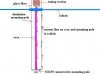
There is a world of differing opinions on the Internet concerning radials, but most are discussing ground radials rather than raised radials, and in my mind there is a big difference, and the world of CB is out there trying to compare these two entirely different setups like they were the same thing.

Call me curious, come right or wrong, but I don't tend to ignore opposing ideas...just out of hand.
 
Last edited:
Height does effect TAO, no debate there.

Ground radials? The other half of the antenna per say.

Many verticals, ham antenna's included use the coax shield as the counterpoise, the coax radiates just as much if not more than the antenna itself. It is designed that way from the manufacture.

A no ground radial antenna is half the antenna.

Using ground radials on elevated verticals, in some situations help prevent CMC, Imax 2000 etc type antennas. Do they increase the performance? Maybe, by forcing the current onto the ground radials instead of the coax.

The current then becomes symmetrical per say and this results in a cleaner pattern of radiated signal.

Some will argue that their vertical with no ground plane out performs a vertical with a ground plane. I always ask "In what direction?". As a no ground plane vertical is left to radiate in a direction effected by the surrounding soil conditions, type of install and many other variables.

A vertical ground plane radiates poorly in all directions if properly installed.
But they do radiate.

Hey wavrider, have you ever tried using the coax shield as the ground plane or the other half of the antenna on a 1/4 wave radiator?

This is an example for why I suggest to Booty Monster that radials don't always respond the same on all end fed vertical monopole antennas.
 
Marconi wrote
Hey wavrider, have you ever tried using the coax shield as the ground plane or the other half of the antenna on a 1/4 wave radiator?
Did he ever have a choice?:oops:
 

dxChat
Help Users
  • No one is chatting at the moment.