
You are using an out of date browser. It may not display this or other websites correctly.
You should upgrade or use an alternative browser.
You should upgrade or use an alternative browser.
-
You can now help support WorldwideDX when you shop on Amazon at no additional cost to you! Simply follow this Shop on Amazon link first and a portion of any purchase is sent to WorldwideDX to help with site costs.
Royce 1 673 mod pll sardine can
- Thread starter Staybolt
- Start date
Assuming it is the same sardine that is in the 621 with the M58473P PLL, the mod for this radio (which is very poorly explained) in Vol 3 pg 52 of Secret CB looks like it brings pin 17 of the sardine (which is Vcc after an internal 120Ω resistor) to pins 5 and 6 of the sardine (which go to binary inputs P5 and P6 on the PLL chip) to bring them high.
Perhaps the function of that mod is described elsewhere in Secret CB, but it isn’t explained where the “By Radio” index takes me.
It wouldn’t be too difficult to figure out what that mod does and if there are other ways to do it, but I would want to know what the crystal frequencies are inside the sardine can along with the part number on the PLL chip so I know if I am looking at the right sardine schematic.
A good pic of it would be cool too")
Perhaps the function of that mod is described elsewhere in Secret CB, but it isn’t explained where the “By Radio” index takes me.
It wouldn’t be too difficult to figure out what that mod does and if there are other ways to do it, but I would want to know what the crystal frequencies are inside the sardine can along with the part number on the PLL chip so I know if I am looking at the right sardine schematic.
A good pic of it would be cool too
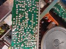
I have not seen that sardine before, but I am fairly certain I see enough to figure it out. I am going to start in on the excel calc now. I can see that this PLL has 8 binary inputs with #7 being tied low and #8 tied high all the time, so I am hoping that is enough to figure out the rest without seeing which divider pin was used on the TC8052P reference divider (not pictured).
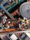
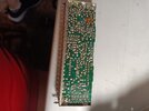
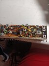
Since you have the sardine out, could I trouble you for a full pic of the front and back of it for my own curiosity? It would also serve as a sanity check seeing if they took the 10kHz or the 5kHz from the divider.
edit: and dont put that sardine back in yet, the mod will likely involve having it out
Thank you for the pictures! I just got done figuring it out and have built the calculator.
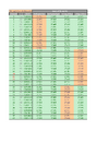
Attached is a excel spreadsheet relating the binary at the PLL chip itself. My math sheet is a bit messy so I just copied the pertinent data to a clean sheet, so there is no math happening on it.
Here is the thought process I used to figure it out.
Since it can be clearly see that pin 8 of the programmable divider is pulled high and pin 7 is pulled low all the time, this suggests the divide by N value must be between 128 and 191. If the PD is 5kHz, then that means a loop frequency range of .64 to .955MHz and if the PD is 10kHz, then 1.28 to 1.91MHz. We also know it is a 23ch AM radio, so the output range, as is, is 26.965 to 27.255MHz. Now we need to figure out what mixing scheme works for those possible ranges, and I believe it is the same general scheme as in the 621 sardine.
If we take the difference between 36.38MHz and the desired frequency, then subtract from that 10.695MHz, we get a loop frequency of 1.28MHz for ch1 and 1.57MHz for ch23, I guess we now know that the reference divider is putting out 10kHz. From there, the binary can be calculated, and I will attach a list of every frequency you can get by manually manipulating the 8 binary input pins.
I need to point out that these binary values are for the pins on the PLL chi, not the sardine can pins. The sardine can only has 1-6 and 5-6 are in reversed order. Also, because the 11m is not in consecutive 10kHz steps, the wiring in the encoder will probably cause some issues, so for simplicity, in the attached chart I will highlight the current channels and what happens if you leave P1-P6 alone (controlled by the encoder) and only manipulate P7 and P8 (but see my next post as it is better to manipulate P5 and P6 as mentioned in Secret CB).
You will want to scroll down to line 128. Hope this helps.
Attachments
Last edited:
Edit: Now we know why Secret CB talks about modding P5 and P6, because messing with P7 and P8 is nearly useless as it moves the frequency so far that VCO lock and BW may become an issue.
Last edited:
And if P5 and P6 are in fact what we care about modding, then I believe it is safe to put the sardine back in as is. Had to be sure. Thats a lot of pins to desolder. You juts gotta look at the chart and be sure you can get what you want on just P1-P6 without messing with P7 and P8.
Thought it was 23, anyhow, it fits the math. I will turn it into a pdfIt's a 40 ch cb...
Heres the binary to frequency chart in pdf format
If you end up cutting the traces and installing switches to manually control the state of P5 and P6, when using the stock channels, you need both P5 and P6 low for ch 1-13, P5 high and P6 low for ch 14-27, and P5 low and P6 high for ch 28-40.

If you end up cutting the traces and installing switches to manually control the state of P5 and P6, when using the stock channels, you need both P5 and P6 low for ch 1-13, P5 high and P6 low for ch 14-27, and P5 low and P6 high for ch 28-40.
Attachments
Last edited:
dxChat
- No one is chatting at the moment.
-
-
dxBot:63Sprint has left the room.
-
dxBot:kennyjames 0151 has left the room.
-
-