• You can now help support WorldwideDX when you shop on Amazon at no additional cost to you! Simply follow this Shop on Amazon link first and a portion of any purchase is sent to WorldwideDX to help with site costs.

SBE Sidebander VI PLL problem

First step in hardware integration, the clarifier. Lee Ho Fuk, that was not fun. But after three nights of fiddling code bits to turn an analog voltage into a consistently repeatable digital number, it works. I'm able to go about 2.5kc off center in both directions and back again.

Kind of got lucky on this one. Whoever had unlocked the clarifier previously had been kind of sloppy and just ran a couple of wires from the pot to the T/R relay. Repurposed those to supply 5 volts to the pot and send the wiper voltage over to Arduino pin A6.

The rest was figuring out how get the digitized numbers to stop jumping around like a kangaroo on a meth bender. Averaging for the win on that one.

Next up, SSB offsets.
 
SSB offsets are in, and they're good. Had to change USB, it was a bit high, dialed in perfectly now. And if I'm wrong, I can always change it. Got lucky here, the mode switch had 12 volts where I wanted to hook in. Found out the CD4049 hex inverter chip that I only used one gate on has a zener diode on every input. Built in level shifting!

Started in on hooking up the channel display and the keypad through the radio. Of course, I screwed something up so I've got to figure that out. The channel display does react when the keypad buttons are pushed, but it's not the right channel, or heading down when I wanted to go up.

Also realized that I never figured out which signal into the old MCU was squelch to stop scanning. So once channels are sorted that will have to be done.

Last step will be hooking up the 19MHz output signal to the original VCO buffer. Maybe by Saturday.
 
Got the keypad inputs sorted out, had to move two pins in software.

Channel display still not right. I think the tens digit of the BCD to 7 segment decoders isn't getting the Latch Enable signal, but that's for tomorrow or Friday to figure out.
 
Channel display problem was worse than I thought. One of the wires inside the ribbon cable had broken. Closer look at the ribbon cable showed it to be of primitive construction. Nine bare wires run between two layers of plastic that are in the process of delaminating. Then I spotted where one of the bare wires was just sticking out of the side of the "cable."

So I grabbed an old IDE hard drive cable and cut a chunk out of it. I used that to replace the dying cable, being very careful to observe "polarity," or where pin1 was, at both ends.

It looks sketchy as hell, but the channel display is now completely working. The digits don't behave exactly the same way as the original when you're punching in channel numbers, but the channels do display correctly.
 
Pumped the output of my low pass filter into the old VCO buffer today. It worked.

Every channel receives exactly where it should. Transmit is very close if not spot on. Also, when I hooked the wire up it actually helped clean the signal up a bit.

Now for the bad parts.

Radio is nearly deaf. Receive signal is lost at about -65 dBm.

No AM transmit. SSB is output is less than a Watt. I can hear it on another radio, but there's not enough there to get the frequency counter's attention when pumping in a 1kHz tone. Not sure if it's a dead final or just a bad feedthrough on the board.

Still haven't figured out how the old MCU knew when a signal broke squelch. Should be a signal line somewhere but the schematic only shows a few lines leaving that area that might be it. But then they might be outputs from the MCU. Guess I'm going to have to spend some quality with the scope on this one. Tempted to see if I can just tap into the squelch circuit and then use a gate on the CD4049 chip for level shifting like I did with the mode switch inputs. It would be crude, but effective.
 
  • Like
Reactions: Shadetree Mechanic
I always thought SBE rigs were really cool. Hope you get this one going. Isn't this the big base station with wood case, tons of switches, and knobs, and LED's over every switch? Seems like I remember drooling over it in one of my S9 magazines back in the day.

Pictures?

73,
Brett
 
I always thought SBE rigs were really cool. Hope you get this one going. Isn't this the big base station with wood case, tons of switches, and knobs, and LED's over every switch? Seems like I remember drooling over it in one of my S9 magazines back in the day.

Pictures?

73,
Brett
No, this is the SSB mobile with the keypad on the face. You're probably thinking of the Console V.

I don't have any pics at the moment, mainly because it's been stripped down to the metal chassis and I've been in the guts of it for the last month.

Here's a link to a pic of what it would have looked like new:

A pic of it's base station big brother:

And the Console V, which was the previous generation:

It also had a mobile sibling, the Sidebander V:

Any of these are fun radios to talk on. OK to work on as long as it's not one of the unobtanium parts that go bad, like what happened here. Some techs curse the feedthroughs on the board, but that's only because they break their solder joints and are a pain to figure out which one it is when that happens.

Oh, and if you ever want to buy one, stay away from the guy on fleaBay charging $1500 or more. They're cool, but they're not $1500 worth of cool. Even if the desk mic is included.
 
Figured out part of my deaf radio problem, the cap I was trying to feed the new VFO signal through to the old VCO buffer wasn't passing signal very well. Yanked it out, started feeding the new VFO through the hole that cap was in, now the radio hears down to -83 dBm. Still a long way to go, but it beats the -65dBm that it was at.

Also, found the squelch signal. Pin 24 of the old MCU. Found it the old fashioned way, twist the squelch knob while probing pins. When you see a large, sudden, and repeatable voltage change that appears to be in response to the squelch knob turning, that's probably it.
 
More deaf radio, T103 was way out of adjustment. It now hears down -113 dBm, or about 0.5 microvolt. Not the greatest I've ever seen, but it is slightly better than the published spec of 0.7 microvolt for AM. SSB I can hear the beat frequency from the AM carrier my signal generator provides all the way down to -127 dBm, which is as low as it can go.

On the transmit side of things, RF output driver reads as a diode. Not two diodes, just the one. That's probably not a good thing. 2SC1306, although the schematic says it could also be a 2SC2092. Trying to get a replacement from a USA seller on fleaBay with what appears to be a pretty good rep. Might get burned, beats the guy in Shanghai where getting burned is pretty much guaranteed.

I did notice that when I disconnected the driver's legs from the board that it wasn't very tightly bolted to the heat sink. Which could mean heat death from not being able to dump into the heatsink adequately, or this thing was somebody's parts chassis. Considering there's a small rectangle cut out of the case for some reason, parts chassis is not an unreasonable assumption.

Oh, and the meter doesn't seem to work. It swings freely, but doesn't move in response to incoming signals. For obvious reasons, can't check it on transmit right now.
 
Get the meter working on receive. Thought maybe the transistor that drives it had gone bad, parts tester said good. I knew I had signal, so I checked on either side of CR202. One side had voltage, the other didn't. Replaced CR201 and CR202 because they're two thirds of a voltage doubler and the cap was new. Meter started working.

Which is good because I don't have a replacement and those kits to do a fake meter on a tiny OLED screen may be hard to come by right now, being from Russia and all.

Still waiting on the RF output transistors I ordered to arrive. Assuming USPS doesn't "misplace" the package, of course.
 
Received new transistors today. Put in a new driver, replacing the mica washer and heat sink goop with a silicone pad. Had to redo the heatsink goop on the bias diodes, too. Old stuff was looked contaminated and crusty.

I probably should have checked the final first but because I'm impatient I fired it up and got Watts out! Because some of you will want numbers it's 2.5 swinging to 5 AM, about 14 PEP on sideband. Yeah, AM is a bit out of whack but that's par for the course on this one.

Just need to figure out what the mess with the speaker wires is all about and I'll have a working SBE Sidebander VI.

I'd say they don't make 'em like this anymore, but it's pretty obvious they didn't actually make 'em like this in the first place.

Other still to do items, replace final mica washer and goop with a sil pad, tidy up wires for the VFO board, try to figure out an alignment, replace the 5 burned out light bulbs, put faceplate and knobs back on, put it on the air and make a contact, and take pictures of it.

Late edit: Almost forgot, and replace the power cord.
 
Last edited:
I have to say, I enjoyed reading this. You have a lot of patience, more than I do these days. What you did was very impressive. Congrats to you!
Thanks!

I'm hoping to encourage more people to give this kind of stuff a go. I could have just thrown in the towel once I discovered the PLL was dead and replacements are at best hard to come by. But for maybe $20 in parts and some time, OK, about 40 hours worth of time total, it was possible to turn a paperweight back into a functioning radio.

I had to learn how to program an Arduino to control the Si5351 chip. Also, it's been probably 5 years at least since my last Arduino project, so I had relearn pretty much everything there. A lot of searches for very basic code examples were involved. Point being, anyone with the skills to work on a radio and surf the internet could replicate my results or do even better. As long as you're willing to learn it can be done.
 
Got the Sidebander VI on the air today and made two contacts. 121 somewhere north of "C-town" (probably Chicago) and UDX-791 in the Gulf Islands off British Columbia. Both said it sounded good.

Unfortunately once in the real world my channel display went wonky. So I'm back to 75% done. It's looking like intermittent crossed wires, I just haven't found them yet. Guess I need to put "learn to solder properly" on my to do list.
 
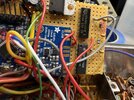
I promised pics. So I'm delivering pics. First up, my crappy little perf board.
IMG_1711.jpeg
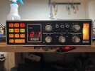
Wonky display when first switched on. That should be channel 1, not 21.
IMG_1712.jpeg
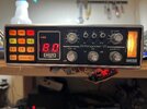
Highest channel when the channel display is working.
IMG_1713.jpeg
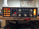
I will get this thing to 100%. Because there's no excuses on da bowl.
IMG_1714.jpeg
 

dxChat
Help Users
  • No one is chatting at the moment.