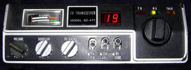
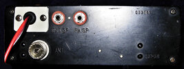
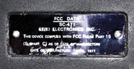
I would put this radio in the rare category. Before now, I never seen or worked on one before. Looking at the data plate, it was made during the early transition to 40 channels. To get more acquainted, I decided to do a full restoration. Several apparent faults needed to be corrected first. The odd ball power plug was destroyed. The photo will show that I replaced it with a plastic plate and grommet. The previous owner tried to fix the power connection by placing two red wires, one stuck out of the external speaker jack, and the other out of the PA jack. It’s not the first time I saw that nonsense. The result was a shorted protection diode along with an open trace. The second obvious fault was a bent over volume control shaft and three missing control knobs. Unless I can find some originals, the knobs on the radio came from a Cobra 19 plus parts radio. IMO, they look better than the originals anyway. Besides re-cap job, I did my usual replacement of the DIN jack to a Cobra 4 pin conversion. New bypass caps were also added to the new mic jack. The re-cap took extra time. Since the pin holes on the board were unmarked, extra care was taken before the electrolytic caps were pulled. This process was supplemented by sketching all the original cap polarities on paper.
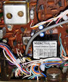
The engineers made no shortcuts on this radio. There’s very high quality throughout, but the radio does have some unusual quirks. It has a proprietary part that I never seen before called an “automatic modulation control.” I wasn’t able to find any info on this part, but by hearing the clicking sound it makes, there’s obviously a relay inside.
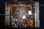
As seen in the photo, the driver and final transistors are fully caged, and they’re difficult to service. They’re attached to the radio’s back plate that is made of thick aluminum. To gain access to this area, a number of wires need to be un-soldered on the print side of the board before the back plate can be removed.
The odd sized red LED readout is all one piece. No lens is attached to the LED or filter attached to the bezel. Fortunately all the segments are working. I was grateful that I didn’t need to retrofit something else. Tracing out and soldering all the individual segment connections would be a killjoy, especially without a schematic.
Like small feet, the speaker side of this radio has half inch protrusions placed on each corner. They’re stamped right into the cover. This allows some breathing room for the speaker if it’s placed on a table. It’s a very thoughtful feature that probably didn’t add any extra expense during manufacture.
IMO, most radios should do the same.
Not many radios like this one include an IC socket for its PLL.
A few cracked slugs were replaced with the same IF can slugs that were used in some of the early 23ch Cybernet boards.
Audio IC: AN315
PLL: MSM 5807
Final: Motorola MPS-U01A ….Replace with 2SC1306
All Motorola transistors like the early Cybernet radios.
So far I’ve been very satisfied with the overall performance of this radio, particularly the receiver. It should be considering the amount of IF stages this one has. For durability reasons, I’m going to leave it connected on-line for a few more days before moving onto something else. To make my archive complete, I’m still looking for a schematic. Like most early Japanese radios, a schematic was usually included with the owner’s manual.


