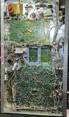
Guys I have a D201A I believe is the late model from the extra trimmers on the bottom?
im having a few issues.
1) meter pins far left all the time. I replaced V401 & V602 from a working D201A but still the same issue.
2) When radio is just sitting monitoring I hear the normal static on channels 1-12, 21-30 but no static on 13-20 & 31-35.
my TX is same 2.5watts dead key on all channels.
That's a later model, as it has fixed bias for the audio tube. The yellow cap, blue thumb wheel, electrolytic cap and a few resistors on the audio board are the giveaway. The D201A doesn't use the "B" side of those two tubes to control the meter like the 23 channel radios did. It uses a UA741TC op-amp, which is labeled Meter AMP U400 on the schematic. If that chip is bad, the meter won't work. It could also be that C450 or C451 are bad, but it is usually the op -amp. It fails if there is a short in the 14.4vdc circuit or the radio has been turned on when the BA board has been removed, as the 14.4vdc comes from the BA board. The fuse (F2) right behind the speaker is an AGC-1A, which protects the 14.4vdc circuit. R422 is the adjustment for setting the meter to its zero reading and R429 for its S-9 reading. The Tram owner's manual explains how to do the alignments and explains how all the circuits work in the radio and has troubleshooting help. The section on the S-meter has the wrong components listed. The S-meter circuit components should be labeled 400s and not 800s. 800 labeled components are for the noise blanker circuit. U801 should be U400. Also, the resistors in the circuit description should be R449 and R450 and the caps should be C451 and C450. The manual will show R422 for zeroing the meter but the parts list and the schematic show it as R450. R422 was the designation for that trim pot on the 23 channel D201 and got carried over into the D201A manual by mistake.
The reason you may not be hearing anything on certain channels could be the channel selector. The black channel selector was notorious for this. Many never worked from day one. The gray selector which came out in the very last of the D201As was much better. Sometimes if you wiggle the knob just a little, they will work. They can be taken apart and cleaned, and there are probably videos on YouTube showing how to do this. The very first D201A I worked on was in 1979 and that black channel selector was the problem. It wasn't dirty inside, but the fingers weren't making contact and needed a little massaging. Just be sure to label the sections before taking it apart so they go back together in the correct position and order otherwise the first time you turn the knob you will trash the selector.
Each crystal controls 4 channels so when you have 4 channels in a row that don't work such as 13-16,17-20 or 31-35 those crystals may be bad, but it could also be the channel sector causing it which is most likely.
I should add that if the op-amp needs replacing, solder an 8 pin IC socket on the board to put the chip into. That way if the chip ever needs replacing again there won't be any soldering needed and less chance of damaging the traces.