• You can now help support WorldwideDX when you shop on Amazon at no additional cost to you! Simply follow this Shop on Amazon link first and a portion of any purchase is sent to WorldwideDX to help with site costs.

Tuning / Modifying a TPL UHF Amplifier

RFEverywhere

Member
Feb 28, 2014
25
0
11
Los Angeles
Hello Guys (& Ladies),

Some help with this issue will be mucho appreciated.

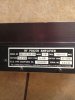
I got a good offer to buy a variation of the TPL UHF amplifier PA6-1AC. The unit label says 400-512MHz with a sticker on the other side saying pretuned for 403MHz to 423MHz. Below is the basic specification for the amp.

I had purchased some VHF TPL amps in the past and retuned them for the ham band without any problems. So I figured I'd be able to do the same with the UHF one. Unfortunately the UHF model is a totally different layout and design and I have not been able to tune it to the ham bands at all whatsoever. Normally there are a couple of variable caps on there that will allow you to tune it but the variable caps on this model only adjusts the input and output impedance and a little bit of output power.

I am fairly new to amplifiers, so I am not sure of anything. Don't know if they are using a LC circuit for the tuning or not, or whether you even use a LC circuit in an amplifier or not.

I think all I need to do is to swap out a capacitor, and/or one of the inductors but don't know which one(s).

I have confirmed that the amplifier works well within the 403MHz to 423MHz but anything above about 423.4MHz and there is no output.

I called TPL and the engineer was nice but wouldn't give me any info and was trying to get me to send it in. I don't care for the $50 they will charge me but I really want to get my feet wet in the amplifier part of this hobby. He said that you can only tune it within a 20-25MHz bandwidth which is perfectly fine.

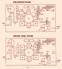
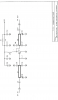
Anyhow, below are some photos and schematics. On the photo with the 2 boards, the variable caps are C2 & C9 on both boards.

SPECS:
Model # PA6-1AC-SSR-SPA
Mode FM
Freq 400-512 adjusted to 403/423 MHz
Volt 13.8VDC
Input 1-6W
Output 25-50W

Thanks for any help!!
 

Attachments

  • 2014-06-29 05.44.25.png
    2014-06-29 05.44.25.png
    546.9 KB · Views: 553
  • $_3 (6).JPG
    $_3 (6).JPG
    68.1 KB · Views: 601
  • $_3 (5).JPG
    $_3 (5).JPG
    62.3 KB · Views: 685
  • 2014-06-29 06.12.43.png
    2014-06-29 06.12.43.png
    252.1 KB · Views: 884
  • 2014-06-29 06.11.53.png
    2014-06-29 06.11.53.png
    354.7 KB · Views: 467
Last edited:

As I look at the strip lines (Z1 and Z2) it does not appear that their length was intended to be adjustable. This suggests that the entire alignment could be done with the adjustment of the 4 variable capacitors. The problem is if you go too far outside the tuned range and any one of the four caps are too far out of adjustment, it won't make power their. You may have better luck bringing the frequency up higher in stages. In other words increase the frequency until you see power starting to drop off and realign for normal power. Then increase the frequency again and repeat. If you find any of these 4 caps tune at minimum capacitance, this would indicate further modification is necessary.
 
Exactly. Some of the fixed value caps may need to be subbed out with slightly smaller values if the trimmers will not bring it into range. I moved a 2m amp to 6m by adding some extra fixed value and also moved a 10m amp up to 6m by removing some fixed caps. Frequency excursions that extreme can't be done a little at a time very easily however this TPL amp should at least come close to start off with.
 
Components Values May Help?????????????????????

Hi. Thanks for the reply and confirmation.

Yes, that's what I figured. However, my problem is that I am not sure which caps are in there for the frequency bandwidth and which are there for the bias. I have looked online everywhere for some sort of diagram that provides that information, but have not been able to find one yet.

I have a RLC frequency calculator that I can use to determine the caps I need to use to obtain a certain frequency, I have tried to use that along with my inductance meter to determine the value of the inductors used nothing adds up to the frequency that it's tuned to. So this is the reason I'm lost.

Can anyone point out which capacitors, resistors, and/or inductors are there to set the frequency? And I am guessing that this would be on either the driver or final boards which I had attached a diagram of in my original post. Also, just like a L/C or RLC circuit, the capacitors would be either parallel or in series with the inductors... No? I mean they will not be capacitors going to or from ground. Correct? If I can eliminate the ones that I am sure are not associated with change in frequency, then, maybe I can figure it out.

There is also a filter board/circuit in the amp and it's configured from 340MHz to 480MHz, so this would obviously have nothing to do with it since it's a low pass filter and covers the ham bands anyway.

I have also attached the component values in hopes that someone can help me.

I just thought of this: Maybe I will start going through the component values one by one based on what the manual says and what is actually inside the amplifier. When I arrive at the one or two capacitors that don't match what the manual says, then bingo!!!! No? It's a shame that I'm on a trip right now and won't be back to try that until the 15th :headbang
 

Attachments

  • Component Values 1.bmp
    1,003.8 KB · Views: 434
  • Component Values 2.bmp
    831.2 KB · Views: 334
Last edited:
As I look at the strip lines (Z1 and Z2) it does not appear that their length was intended to be adjustable. This suggests that the entire alignment could be done with the adjustment of the 4 variable capacitors. The problem is if you go too far outside the tuned range and any one of the four caps are too far out of adjustment, it won't make power their. You may have better luck bringing the frequency up higher in stages. In other words increase the frequency until you see power starting to drop off and realign for normal power. Then increase the frequency again and repeat. If you find any of these 4 caps tune at minimum capacitance, this would indicate further modification is necessary.

Sorry. I missed this post earlier. That is true and a great idea too. I will try it once I'm back from the trip. However, the service manual says that those 4 capacitors are specifically for input and output impedance matching. Please see attached. With that in mind however, I am willing to basically try anything.
 

Attachments

  • TUNE_UP_INSTRUCTIONS.bmp
    673.9 KB · Views: 496
  • DESCRIPTION.bmp
    1.4 MB · Views: 418
I'm just assuring you it is those 4 variable capacitors that adjust the frequency of operation. If TPL was less worried about the $50 charge, they would have told you the caps adjust the frequency of operation. Instead they gave you a technical response of saying they adjust the input and output impedance which means exactly the same thing in this case.
 
I'm just assuring you it is those 4 variable capacitors that adjust the frequency of operation. If TPL was less worried about the $50 charge, they would have told you the caps adjust the frequency of operation. Instead they gave you a technical response of saying they adjust the input and output impedance which means exactly the same thing in this case.

Shockwave, you know, as I read what you wrote, I kind of started to think that, but I started to tell myself I was probably wrong and should ask. Funny thing is that I tried to adjust them before and I still got nothing, but when I think about it now, I was not taking my time and doinh minor adjustments. I was turning them fully one way or another like a moron. I should go back and spend some time on it and make small adjustments from the current frequency range and make my way up to the ham band.

Anyway.....

You my friend are a true gentleman and scholar, and any other good terms that's out there. I want to thank you for taking the time to post even though you did not have to. I appreciate you for causing the light bulb in my head start to turn on sir!!!!

Have yourself a great weekend and keep knocking them out.

I can't wait to travel back home after next week and pop that thing open to try and tune it (hopefully) this time as I have some ideas both from this threat and just thinking about it on how I will go about it.

Many many thanks!!!!!!

HAPPY 4TH OF JULY
What was the outcome? Did the adjustments work? You left everyone at the edge of their seat for years.
 

dxChat
Help Users
  • No one is chatting at the moment.