• You can now help support WorldwideDX when you shop on Amazon at no additional cost to you! Simply follow this Shop on Amazon link first and a portion of any purchase is sent to WorldwideDX to help with site costs.

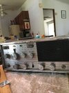
Utica, Town and country 111 cb radio. shorting out.

klj2497

Active Member
Jan 19, 2017
222
47
38
60
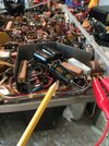
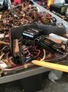
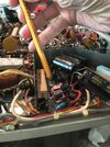
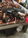
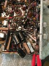
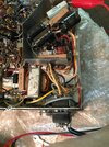
Hello my friends, im reviving a Utica TandC 111. the 40uf 450 vdc, capacitor, i'm pointing to in the picture, and the 2/ 10uf resisters also pointed to in the photos. are connected to the red 2 wires from the transformer. when i tried to bring it up slowly on the variac. but they started smoking at about 30vac. It looked like it was messed up before it got here. i replaced the 2 20uf and the 40uf 450 vdc I tried to give just enough ac to get a measurement. the three start to get warm at about 20vac. i noticed that on the 2 10uf resistors i am getting dc voltage and ac voltage. of 15vdc and 20vac. I saw the light bulb was on and i measured negative volts in the right places. IMG_4415.JPGIMG_4419.JPGIMG_4420.JPGIMG_4421.JPGIMG_4417.JPGIMG_4416.JPGIMG_4418.JPGIMG_4342.JPG
 
Last edited:

Leads me to suspect that the rectifier diodes are shorted. The metal-can "top-hat" package was a first-generation rectifier component that was too delicate to survive a shorted filter capacitor.

Leads me to suspect the radio would work better if the filter caps had been replaced before the old ones shorted and caused collateral damage to the rectifiers.

We use a generic 1N5408 3-Amp rectifier. Never mind the radio's B+ circuit would never draw even close to 1 Amp. They are generic, cheap and sold by zillion sources. The added current rating is cheap insurance. Really cheap.

I won't bore you with how to test a diode with a multimeter, but if you just use the OHMs scale and show a short across even only one of them, this is all you need to know.

And if only one of them shows shorted, you replace them all anyway. A surge that killed one diode probably travelled through the other ones. Tends to weaken a part it doesn't kill. Replacing them all is just cheap insurance.

Sure, I could be guessing wrong here, but this is what it sounds like.

One last thought. If enough AC voltage was put across the DC-only electrolytics this can cause permanent damage to the part. How much is enough? No idea.


73
 
  • Like
Reactions: BJ radionut
Thanks my friend. i'll check the doides . i have an order of 10uf 1/2watt resistors. and some 40uf 450vdc. capacitors just in case. lol
 
Two of the diodes, in the radio measures about 1.2 meg. ohms. The other two show 1.9 meg. ohms I'm ordering some new diodes. also, i used a diode tester on my fluke. all 4 beeped, and are in the .546 ohm range.
 
Last edited:
Yep, it didn't take much for that one capacitor i did measure about 3.5 volts ac on the capacitors. and 20 vdc also. the variac was at 20volts also. idn
 
I replaced the diodes, no change. I get -35vdc where it should be -15. im only giving it 90vac from the variac. strange the dc voltage is a little higher after the 10uf resistor coming from the red transformer wire. It should be lower i believe.
 
Last edited:
This is a really wacky one. The rectifier circuit is a full-wave center tap circuit. Most folks ground the center tap and take positive B+ from the rectifiers.

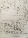
This radio does the opposite. Sorta. The rectifiers X3,4,5&6 are feeding negative voltage to a 250 ohm resistor, then through it to ground. The voltage drop across the resistor is used to derive negative 15 Volts while transmitting.

The transformer winding's center tap is the positive output from the B+ circuit. Feeds into a 40uf cap C1A and into the filter choke L20. What comes out of L20 gets split off from there. I should point out an error in the diagram you posted. The filter cap C2A has the polarity printed backwards. It has the positive side grounded, the negative side hot. THIS IS NOT WHAT'S IN THE RADIO! At least you hope it isn't. If you installed this capacitor the way the diagram shows it, IT'S DRAWN BACKWARDS!

Yep, the negative side of C2A should go to ground, the positive side being fed from L20.

This is one oddball design, even without a fatal typo in the schemo.

73
 
Thank you my friends. As young Anakin would say, its working! i switched the c2a and Hot dog. and i only burned up 5 capacitors...... awsome!
 
Last edited:
Now im trying to loosen up the channel knob where it connects to the crystals i sprayed electic cleaner. but it didnt work. i think its seized where the shaft goes thru. i may have to take it apart.
 
Thanks nomadradio. I got it loose. And very thing is working, but it does not change frequency when i change channels. it stays at 26.9350, with the antenna cable removed. with the antenna plugged in it is 13. 4534 . also no receive.
 
I traced it down to the crystal bank, im not getting voltage from there to the v3 tube 2 pin. the rest of the voltages are okay on v3. it is -.452vdc. It should be -3vdc
 
Anyway, I got the transmit working. the dial is 2 channels off. but still no receive. Thats a big section too. The negative ground connection between the crystal bank, and the radio was not soldered. Now it is. i think it helped. but still no rec.
 
Everything works now except for the rf gain, and the receive. the crystal bank seems to be working. but, the rfgain doesn't work. feels like theres nothing inside. someone may have sprayed wd or something, or maybe it got scorched i'll have to change out that rf gain
 

dxChat
Help Users
  • No one is chatting at the moment.