• You can now help support WorldwideDX when you shop on Amazon at no additional cost to you! Simply follow this Shop on Amazon link first and a portion of any purchase is sent to WorldwideDX to help with site costs.
  • Click here to find out how to win free radios from Retevis!

Anytone at-5555n II (version 2)

About the Q5N2, I just bought two of them. I received the long version, but I also bought the QT60 and received the pro version, which is the Q5N2 short version. They are nice radios. I have the Lincoln 2+ with RWOB and NPC mods, and the modulation is higher than the Q5N2 or QT60P, but those two are definitely great radios. I tried the NPC mod from the Q5 Plus thread in the Q5N2, but I didn't see much of a difference, to be honest, so I removed it. I did the AM modulation mods in the service menu but nothing else. I can see my three radios peak in AM about 70W PEP on a Bird power analyst, not the 43P. The Bird is very well calibrated, and I'm happy with that. The Lincoln gets about 50W PEP. I don't know if I can push it more in the variables inside. I did the RWOB and set up the maximum average power the same as without the RWOB. I see more PEP, which is fine.

I hope I can get some advice, but probably I'm not going to do anything else to those radios. By the way, the Lincoln was secondhand, and the echo doesn't work. It's a little hard to find the problem in those tiny parts.
 
Here are the readings. I tested both with black to source and again black to ground. Same results.

Q101 3.595 volts
Q102 3.595 volts
Q103 4.058 volts
Q104 3.854 volts
Q109 1.2991 volts
I don't think this is your issue, but for a matched pair, Q103 & 104 don't seem to be very well matched.
 
  • Like
Reactions: VJV
Thanks SL. I didn't have the radio to open up.
I didn't have mine open, but Timmy posted a pic in this thread that I looked at. I sort of recalled that the part designation in the PA were descending, or I would have assumed the same as you did.
 
the matched pair is 101 and 102.

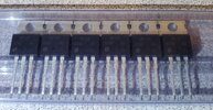
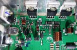
It's raining here today, I've already watched the F1 race in Spa and I am now bored. So, I have decided to replace the IRF520s in the Q5 (Q101, Q102, Q103, Q104) with some new leftovers I have on hand, re-check the bias and see what happens. They are Vishay Siliconix, P/N IRF520PBF-ND and are all stamped N26K. I bought them from digikey.com last year.

Is there something special I need to do to decide which four of the six of them to select, especially when it comes to the matched pair in Q101/Q102?

IRF520_Vishay - Copy.jpg

Q5N2_IRF520 - Copy.jpg
 
I have been asked what I am using for a power supply. I have tested with a Megawatt S-400-12, a PowerMax PM4-120 and also a 12 volt battery out of my F150. It has also been tested by a tech using his own power cord and power supply.

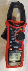
When I test the current draw at the Q5's full RF power into a dummy load using the clamp meter shown below (clamped at the tip around the positive lead only), the meter shows 1.98 amps on AM and 3.2 amps on SSB.

Kaiweets_HT206D_ClampMeter - Copy.jpg
 
3.2 amps on SSB.
Something is very wrong ! 3.2A at 14 volts is only 44.8 watts total. Assuming about 70% efficiency that's only 31 watts making it out the antenna, which is only half what it should be doing.
AM Power draw is close to what it should be, so it does seem that whatever is causing the problem is in the part of the power circuit that feeds only the SSB transmit part of the radio.....
Pretty sure replacing the finals isn't going to do anything at all ! I would be trying to figure out which filters/caps etc. are feeding the SSB transmit stage as that is where the problem will be.
 
  • Like
Reactions: TimmyTheTorch
I have been asked what I am using for a power supply. I have tested with a Megawatt S-400-12, a PowerMax PM4-120 and also a 12 volt battery out of my F150. It has also been tested by a tech using his own power cord and power supply.

When I test the current draw at the Q5's full RF power into a dummy load using the clamp meter shown below (clamped at the tip around the positive lead only), the meter shows 1.98 amps on AM and 3.2 amps on SSB.
It's raining here today, I've already watched the F1 race in Spa and I am now bored. So, I have decided to replace the IRF520s in the Q5 (Q101, Q102, Q103, Q104) with some new leftovers I have on hand, re-check the bias and see what happens. They are Vishay Siliconix, P/N IRF520PBF-ND and are all stamped N26K. I bought them from digikey.com last year.

Is there something special I need to do to decide which four of the six of them to select, especially when it comes to the matched pair in Q101/Q102?

View attachment 69593

View attachment 69594

View attachment 69595
The clamp style meters are BS when measuring DC. Hardwire your test leads to the radio.

I think you should invest your time in performing the bias procedure, rather than shotgunning the FET's.
 
Something is very wrong ! 3.2A at 14 volts is only 44.8 watts total. Assuming about 70% efficiency that's only 31 watts making it out the antenna, which is only half what it should be doing.
AM Power draw is close to what it should be, so it does seem that whatever is causing the problem is in the part of the power circuit that feeds only the SSB transmit part of the radio.....
Pretty sure replacing the finals isn't going to do anything at all ! I would be trying to figure out which filters/caps etc. are feeding the SSB transmit stage as that is where the problem will be.
Yeah, I lost my ambition to swap out the finals as soon as it stopped raining.

If anyone on here has a lead on a tech that wants me to send this radio to them and repair it if it's not too costly, please let me know. I'm not asking for a freebie, I believe in paying a person for their time and expertise.

I hate being wasteful and if the right person works on it, I figure it'll come back to me as a radio that will do more than what I want it to do. i.e. a clean signal with great modulation. I don't need the radio to crank out 80 watts or whatever bloated amount on its own. I can just turn the RF power down some to safely drive the Carl Built 200HD with what I seem to remember has the 2SC2879 transistors.
Do the BIAS ALIGNMENT! Then see what happens.
 
  • Like
Reactions: TimmyTheTorch
I went through and checked the bias again. Here's what it says. I used three different meters and they were within a few ma of each other on each IQ.

TX-IQ1 -> 102 ma (close to 100)
TX-IQ2 -> 49 ma (close to 50)
TX-IQ3 -> 10 ma unkeyed, 30 ma mic keyed (unkeyed value + 20 should be close to keyed value)
Just my observation regarding the Final Bias setting on the Q5N2 and QT60. I know Mark said it is +20ma but I think that is a little low. I think +30~40ma is closer to the factory setting. Also, remember he was doing this on a Stryker 955 which Stryker recommends running at 14.2v.

I haven't taken the time to check a "factory" setting and I could be totally wrong. If someone has checked the "factory" Bias setting on one of these two radios, please share and what voltage was used.
 
Last edited:

dxChat
Help Users
  • No one is chatting at the moment.