You are using an out of date browser. It may not display this or other websites correctly.
You should upgrade or use an alternative browser.
You should upgrade or use an alternative browser.
-
You can now help support WorldwideDX when you shop on Amazon at no additional cost to you! Simply follow this Shop on Amazon link first and a portion of any purchase is sent to WorldwideDX to help with site costs.
ARF 2001 in progress
- Thread starter TM86
- Start date
Found some 12.096 MHz crystals for sale, bought 2, just in case. They arrived today and I decided might as well find out if that's the problem or if I just need to add a trimmer cap.
While removing the old crystal I think I may have accidentally found the root of the 10 kHz low problem. Both solder pads for the crystal looked like they had been worked on before. Went to desolder the one closest to 4L3, and it came right off the board. The only thing holding it in place had been the solder. The other pad wasn't in much better shape.
Anyways, got the new crystal in, fired it up and it was on the right channel for transmit and receive. There's still a weird delay where it goes off frequency when switching from transmit to receive, but that's a minor problem compared to where it was.
Now to figure out why the transmit and receive signal levels are so low.
TL;DR: It works! Sort of.
I'll have to dig this link up when I need more crystals. Mouser's price is cheaper than what I bought, but it would cost more in postage than what they're worth to get a refund.
I do at times, too. Which probably isn't the smartest move since I work for one of their competitors.I buy other components from them in bulk, too.
Who I'm not going to name.
May have figured out the problem with transmit power being low, radio appears to be massively misaligned. Just by tweaking a few things I managed to get power from one to five watts on a dead key. Problem is, it's supposed to (from the Service Manual) be able to hit around 14.5 Watts in AM as part of the alignment procedure.
It may have been cranked down for use with an amp. Or it may have been someone tweaking to see what would happen. Hard for me to say.
I've ordered some alignment tools with hex ends (part of a larger set) to help with getting this sorted out. Provided they actually fit, of course. Had to since nothing I have here that's non-metallic fits and the I don't want to play with metal Allen wrenches in a live chassis. I know, I'm just being paranoid. What could possibly happen, right?
Got the alignment tools, twiddled some cores in the TX chain, no change.
Hooked up Mr O'Scope and checked that each stage is amplifying, which they are. Just not enough to get more than 4 Watts out in any mode.
Did find that a previous owner had cranked A6R4 way over to one side. Since I think that's supposed to have something to do with the AGC circuit, that's probably not a good thing.
Hmmm.... I should probably check the DC voltages on those transistors. Meh, tomorrow, after I've had some sleep.
Finally found the elusive little guy that was giving me so much trouble on setting transmit power. It was a loose nut on the A8 board that apparently either stiffens the board to complete an iffy solder joint or firmly connects that board to ground.
I'm still only getting about 10 watts max out, but considering what I was getting, I'll take it.
The reason for the front panel meter readings being low was previous golden screwdriver work that had turned down A8R5 (TX power) and A8R10 (RX signal level).
The point is, she works again! All I need to do now is wire up a D104 I bought (and fixed) for that purpose and swap out the plastic fronts on the scan and mode switches and she'll be complete.
Other things I had to fix and didn't mention, replaced the power cord, replaced both fuse holders, replaced a broken mini-coax from the A6 board to the A8 board.
Also, removed a relay that was switching the 110V power to an accessory that has long since disappeared. All I know is they drilled two holes in the top of the radio for it. Could have been an amp, could have been a light bulb, no way to know now. Just thought it would be safer not to have a couple of 110V wires with nothing to do hanging around inside the chassis.
No one asked, but here's some pics. The mic is an incorrect TUP9 stand, but the same color scheme as I found in a bit of advertising somewhere. It helps that it was broken when I got it, so it was (relatively) cheap.
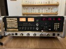
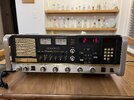
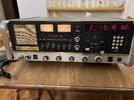
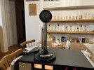
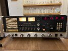
I can see why some people don't like these radios. They're kind of a pain to work on and touchy as hell. The mode and scan switches are just flat out expensive if you can find them, and I haven't seen one of these show up on FleaBay with those switches intact.
But it's complete now. So I can throw it on a shelf and start on the next PITA.
Unless, of course, I decide to put an FM kit in it...
Have a beautiful srf 2001, with everything intact (until I managed to one of the small silver switches ). Problem is that it receives fine, but there's no modulation when I tx - just a carrier. Checked the D 104 that came with it, and afaict it's not the problem.
Anyone have any ideas? It's really a gorgeous radio and I'd like to get her on the air.
Thanks in advance for any help.
Anyone have any ideas? It's really a gorgeous radio and I'd like to get her on the air.
Thanks in advance for any help.
Not going to be the scold here, but you should probably start a new thread.Have a beautiful srf 2001, with everything intact (until I managed to one of the small silver switches ). Problem is that it receives fine, but there's no modulation when I tx - just a carrier. Checked the D 104 that came with it, and afaict it's not the problem.
Anyone have any ideas? It's really a gorgeous radio and I'd like to get her on the air.
Thanks in advance for any help.
Until then, need to focus on what's working and what's not.
We know your audio amp works, because you wouldn't have receive audio otherwise.
Is there any audio coming out of an external speaker when you're in PA mode? If not, the audio is getting killed between the mic and the audio amp.
Is there any RF going out when you're in one of the sideband modes? If it is, then the problem is probably somewhere between the audio amp and the AM regulator.
This thing also has the SAM circuit. I didn't have to trace that out when I was going through my radio, so I don't know if switching that in or out will make any difference to the audio routing coming in to the audio amp. But if it does, then that's something else to look into.
It can be done, if someone is willing to commit enough time and money to the project.TM86: ...are you just kidding, or can that be done. That'd be hallmark.
For FM modulation it would be a matter of figuring out which circuit to inject into, the VCO, or the downmix oscillator. Right now I'd say the VCO is probably the easier one to get to change frequency the way we would want it to, but I haven't played with it.
For FM demodulation we know there's a 10.695 MHz IF (amazing what you can learn reading the manual, I should do that more often) and there's at least one kit specifically for that frequency. So with that kit it would just be a matter of where to grab the IF signal and at the same time disable AM demodulation.
I haven't really thought about it much since I threw that out there. Was kind of hoping someone smarter than me (meaning most of the members here, for starters) would pick that ball up and run with it. All you need is an ARF 2001 and the money to keep buying stuff until you get a working result.

