You are using an out of date browser. It may not display this or other websites correctly.
You should upgrade or use an alternative browser.
You should upgrade or use an alternative browser.
-
You can now help support WorldwideDX when you shop on Amazon at no additional cost to you! Simply follow this Shop on Amazon link first and a portion of any purchase is sent to WorldwideDX to help with site costs.
-
The Retevis Holidays giveaway winner has been selected! Check Here to see who won!
Cobra 29 Constant Key Up
- Thread starter Chris Lawrence
- Start date
Sorry, I failed to mention, I replaced it.try removing the transistor and testing it.
the problem could be the component itself.
LC
NZ8nSo, putting everything else back together, center pin (Collector) of TR21 soldered too, the RED LED stays on or goes out (switches to Green) when you lift one leg of R95?? Or merely unkeys the radio, RED LED still on?
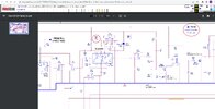
View attachment 58909
That feeds +8v TX to the output pin of the Mixer section of IC3 through L21.
Everything back to stock: Radios stays keyed up. Red TX light is on.
R95 lifted: Radio unkeys (no rf power output) but red TX light still stays on.
Something is "pulling" the Base of TR21 down just enough to cause it to "key" and light the red LED. Half of the Receiver circuits are "fed" from the voltage at the Base of TR21, when you key (TR7, FET1, Base Bias of TR10 in the 2nd IF, maybe a few other places), it shorts nearly to Ground the voltage that feeds them. It also "feeds" the Emitter side of the Mic Preamp, and a few other places. It also feeds the "high" side of the Delta Tune pot.
When I get home, I will dig out a schematic diagram I "drew" on, tracing out the RX and TX paths that spider from TR21. Or redraw it.
When I get home, I will dig out a schematic diagram I "drew" on, tracing out the RX and TX paths that spider from TR21. Or redraw it.
Thanks for that. And FYI all 3 legs of TR21 are w/in .1v of 8 volts at all times.Something is "pulling" the Base of TR21 down just enough to cause it to "key" and light the red LED. Half of the Receiver circuits are "fed" from the voltage at the Base of TR21, when you key (TR7, FET1, Base Bias of TR10 in the 2nd IF, maybe a few other places), it shorts nearly to Ground the voltage that feeds them. It also "feeds" the Emitter side of the Mic Preamp, and a few other places. It also feeds the "high" side of the Delta Tune pot.
When I get home, I will dig out a schematic diagram I "drew" on, tracing out the RX and TX paths that spider from TR21. Or redraw it.
Last edited:
remove TR21 again and measure the voltages on the empty traces.
everything you are saying sounds like a shorted TR21 so we need to see what is going on without the transistor there.
LC
everything you are saying sounds like a shorted TR21 so we need to see what is going on without the transistor there.
LC
I can do that when I get back but the transistor works. I swapped it with another radio with no change. The other radio works fine with the transistor from the nonworking radio. I can’t recall those voltages off the top of my head but I believe the trace for the collector, middle leg, was around 12 V without a transistor in place.remove TR21 again and measure the voltages on the empty traces.
everything you are saying sounds like a shorted TR21 so we need to see what is going on without the transistor there.
LC
my apologies for the statement "everything looks like a shorted transistor".
I should have looked at the voltage chart before guessing, as i would have seen that your voltages look correct for TX, and the problem is that the collector of TR21 is not dropping to 0 volts on RX.
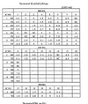
here is a voltage chart that includes IC3, your TX mixer chip.
please check the voltages on all pins of IC3 in both RX and TX and post them here.

If you look at the schematic you can see that pin 6 of the mixer chip should be at zero volts in RX and 7.5 volts in TX.
my guess is that you will find 7.5 volts on this line in both RX and TX.
the fact that R95 being lifted causes the collector of TR21 to drop to zero volts leads me to believe that IC3 might be your culprit.
unless im missing something that is...
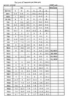
also, just so you have it, here is a list of the RX and TX voltages of the transistors:

let us know what you find.
LC
I should have looked at the voltage chart before guessing, as i would have seen that your voltages look correct for TX, and the problem is that the collector of TR21 is not dropping to 0 volts on RX.
here is a voltage chart that includes IC3, your TX mixer chip.
please check the voltages on all pins of IC3 in both RX and TX and post them here.

If you look at the schematic you can see that pin 6 of the mixer chip should be at zero volts in RX and 7.5 volts in TX.
my guess is that you will find 7.5 volts on this line in both RX and TX.
the fact that R95 being lifted causes the collector of TR21 to drop to zero volts leads me to believe that IC3 might be your culprit.
unless im missing something that is...
also, just so you have it, here is a list of the RX and TX voltages of the transistors:

let us know what you find.
LC
my apologies for the statement "everything looks like a shorted transistor".
I should have looked at the voltage chart before guessing, as i would have seen that your voltages look correct for TX, and the problem is that the collector of TR21 is not dropping to 0 volts on RX.
here is a voltage chart that includes IC3, your TX mixer chip.
please check the voltages on all pins of IC3 in both RX and TX and post them here.
Thanks for that info LC. I’ll check it out and post the findings.
Actually, he said it quit transmitting, the red TX LED stayed on.
Have you recapped it yet?
Unsolder one leg of R70 (330 Ohm) first, (don't cut it, geez!), if you get RX and Green LED back, C67 is shorted. C67 goes "through" R70, then through the cathode of D21. These feed the Mic preamp bias (Ground side) when keyed.
If C67 is "shorted", it might have enough "pull" to turn TR21 on.
The Emitter of TR21 should have +8v constant, the Base of TR21 should have +8v when unkeyed, and nearly +8v, maybe 7.3v when keyed. The Collector (center leg) should only have +8v when in TX (also turns the Red LED on).
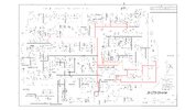
 Red is direct PTT, (through R101, 2.2 Ohms), which also "feeds half of the RX circuits. Orange is path after D21, R70 to C67.
Locations of components I think may be affected. R70 and D21 are most likely ok.

If this does not fix it, we have to go further away and disconnect resistors that feed the RX Preamp or FET1 or the 2nd IF until we find the culprit.
I say it should be a low resistance, as a higher than 2.2k shouldn't trip it. Hence my idea of C67.
Have you recapped it yet?
Unsolder one leg of R70 (330 Ohm) first, (don't cut it, geez!), if you get RX and Green LED back, C67 is shorted. C67 goes "through" R70, then through the cathode of D21. These feed the Mic preamp bias (Ground side) when keyed.
If C67 is "shorted", it might have enough "pull" to turn TR21 on.
The Emitter of TR21 should have +8v constant, the Base of TR21 should have +8v when unkeyed, and nearly +8v, maybe 7.3v when keyed. The Collector (center leg) should only have +8v when in TX (also turns the Red LED on).
 Red is direct PTT, (through R101, 2.2 Ohms), which also "feeds half of the RX circuits. Orange is path after D21, R70 to C67.
Locations of components I think may be affected. R70 and D21 are most likely ok.

If this does not fix it, we have to go further away and disconnect resistors that feed the RX Preamp or FET1 or the 2nd IF until we find the culprit.
I say it should be a low resistance, as a higher than 2.2k shouldn't trip it. Hence my idea of C67.
this is really just for NZ8N so that we don't confuse OP.
NZ8N i didn't see the part where he said he had no TX, must've missed that.
what do you think the chances are of the actual RX/TX LED having shorted internally causing the collector of TR21 to stay high?
sounds weird i know.
LC
NZ8N i didn't see the part where he said he had no TX, must've missed that.
what do you think the chances are of the actual RX/TX LED having shorted internally causing the collector of TR21 to stay high?
sounds weird i know.
LC
NZ8n
Everything back to stock: Radios stays keyed up. Red TX light is on.
R95 lifted: Radio unkeys (no rf power output) but red TX light still stays on.
Looking at the schematic, the Green side of the dual color LED is fed +8v constant through R113 (470 Ohms). The Anode side of D20 isolates that " possible idea" of the Green side being shorted to cause it to key. Voltage drop the wrong way, high impedance that direction, low impedance if/when keyed (PTT). The Cathode of D20 goes directly to the PTT line itself, which "shorts" the Green LED voltage, turning it off in TX. Also not through the 2.2 Ohm resistor (R101). Unless D20 is also shorted?? Highly unlikely, but a slim chance.
The Red side of the dual color LED is fed through R114 (820 Ohms) to the Cathode of TR21.
The Red side of the dual color LED is fed through R114 (820 Ohms) to the Cathode of TR21.
Actually, he said it quit transmitting, the red TX LED stayed on.
Have you recapped it yet?
Unsolder one leg of R70 (330 Ohm) first, (don't cut it, geez!), if you get RX and Green LED back, C67 is shorted. C67 goes "through" R70, then through the cathode of D21. These feed the Mic preamp bias (Ground side) when keyed.
If C67 is "shorted", it might have enough "pull" to turn TR21 on.
The Emitter of TR21 should have +8v constant, the Base of TR21 should have +8v when unkeyed, and nearly +8v, maybe 7.3v when keyed. The Collector (center leg) should only have +8v when in TX (also turns the Red LED on).
View attachment 58941Red is direct PTT, (through R101, 2.2 Ohms), which also "feeds half of the RX circuits. Orange is path after D21, R70 to C67.
Locations of components I think may be affected. R70 and D21 are most likely ok.
I’ve been out of town. Hopefully, I can have this done before I leave again. Fortunately, it’s not time sensitive.
Removed R70. No change. Will continue w/ your additional instructions….


