• You can now help support WorldwideDX when you shop on Amazon at no additional cost to you! Simply follow this Shop on Amazon link first and a portion of any purchase is sent to WorldwideDX to help with site costs.
  • Click here to find out how to win free radios from Retevis!

Cobra 29 LX Max no xmit...

Hawkeye351

Well-Known Member
Jun 27, 2021
569
477
73
57
Got one of these brand new Cobra 29 LX Max radios on the desk today with a no transmit issue.

Collector of Driver in receive mode is around 16v, hmmm...
Collector of driver in transmit mode is 13.4v.

Collector of Final in receive mode is around 6v.
Collector of Final in transmit mode is around 12.5v.

Base and emitter of both the driver and the final in either mode (xmit or receive) stays at 0v, hmmm....

Replaced final and driver with new ones, same result.
Replaced them both again, still same result.

Already checked:
R58, R56, R123, R55, R54, R53, D8...
All tested good with proper values.

The owner said he was talking on it one night and heard what sounded like a toothpick snapping in half, then the transmit quit immediately.

Radio transmit light does come on when keying the mic.
Display shows "Transmitting" when the mic is keyed, but shows no output on the S/RF meter.
My monitor radio shows full scale with good modulation when I key this 29 up on the same channel.

Seems like a bad final or driver, but I've already replaced both twice with new ones, and both sets of new ones I tested on the tester showed as good BJT's with good Hfe's, even the originals that I took out tested as good BJT's with good Hfe's.

No burnt traces, no cut traces, nothing looks blown up, looks like brand new. No mods whatsoever in this radio, all original parts still intact.
 

Only schematic I have is from CBTricks for the 29LX LE with the KEPC-1141-B board. If you have a different schematic, I'd like to take a look at it.

Since both the collectors are tied to the supply via the Vol SW, transformer, D8, and their respective chokes, having 16v there is odd indeed with no modulation. Check the supply to make sure it is not too high. Since the driver and final are basically off without RF from the buffer, I would expect no current to be flowing in either of them during RX, yet, you measure different voltages on them (16v for driver and 6v for final) in RX. Definitely a big Hmmm!

Once in a while, when the mic is unkeyed, it can happen at just the right time when the magnetic flux density in the transformer is high and a back emf spike is created. One of the functions of D8 is to protect the transformer from such spikes. If that diode took a hit and became a 1N4ΩΩ1, it might explain these symptoms (and the snap). It may have even avalanched the final transistor and damaged a choke without totally smoking the transistor itself.

I would start by checking D8 (edit: sorry, I see now that you did that one already, missed that somehow looking up the others), both chokes, and the supply voltage at the supply itself.
 
Last edited:
  • Like
Reactions: Hawkeye351
Collector of Final in receive mode is around 6v.
Was that a typo? Was it meant to say 16v? Maybe the 16v was too much and something else blew that is keeping the RF from the final section and therefore keeping them unbiased and turned off? 16v is too much for that radio according to the OM. You say you have modulation on a monitor radio, so it must be making RF, but where is it disappearing? Do you have any way to trace RF signals?

Different question. Being they are biased solely of RF, and only for brief periods, do you think your meter could even see that change? You may need a 'scope.
 
  • Like
Reactions: Hawkeye351
IF this board is what I think it is, the part that failed is SMD and is in the pre-driver section.

Need a photo of the board to be sure - because it has been known that the LX models have a 10 ohm resistor of 1/8W rating that often pops in the Pre-drivers network - the BASE lead side which grounds itself to the coil leading into the stage (Class C somewhat) - that feeds that 10Ω resistor - that is if it is discrete.
 
My bad,
Collector of both driver and final in receive mode is 13.26v.

Base of DRIVER in receive mode is 0.06v.
Emitter of DRIVER in receive mode is 0.00v.

In transmit the collector of the DRIVER is 12.45v.
In transmit, both the base and emitter of the DRIVER are 0.00v.

Collector of FINAL in transmit mode is 12.56v
Base and emitter of FINAL in receive mode is 0.00v.

Base and emitter of FINAL in transmit mode is 0.00v.

As far as supply voltage, exactly 13.83v DC.

Receive works great.
 
Last edited:
  • Like
Reactions: brandon7861
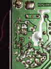
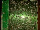
These are the only surface mount components on this one.

Left side of board (radio facing you), near audio IC. And no, that's not a solder joint touching the 2 traces, it's that sticky flux.
IMG_20240212_205032813.jpg

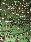
Center of board and around VCO.
IMG_20240212_205021933.jpg


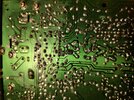
No those are not solder balls, that you may see here and there.

Terrible looking factory solder work.
 
No, you've got discrete!

There's hope yet.

Will need to to locate the predriver and make sure it's producing some form of RF into the next stage which would be the driver.

To help you with that, we will need photos of the top - component - side of the board.

You can check to see if the thing even produces RF by simply using a test probe lead to act like a simple antenna and use a monitor radio to "catch" that mW RF-signal off the Pre-driver - if you hear carrier in TX on the same channel - then the stages after it are the ones that need to be fixed.
 
  • Like
Reactions: Hawkeye351
I do have an oscope (100mhz). It's a digital scope though.

I have an old analog scope too, I unhooked it cause I'm rearranging my desk around.

I can use the digital scope to snoop around that area right, or would the sniffer probe be better?
 
A digital scope would be just fine for following a TX signal through the radio. If you plan to get near the output network with it, be sure to use the 10x setting (should be anyway to not load down stages). Digital and analog scopes have limits and are often rated in max volts, max dBm or max mW. Be sure to respect those limits when playing around the finals! For example, my digital scope has a max rating of 20v. To put that into perspective, a 4w carrier into a 50Ω load is sqrt(4w*50Ω)=14.2v peak. If I were probing the output jack with a 1x probe and gave it modulation on accident, the 16w peak RF equates to 28.3v peak and a cooked front end on the scope. Add a reflection from an SWR issue and you can double that voltage!

The only scope I own is a digital USB one, it has served me very well. I've never owned an analog scope :( In fact, sadly, I've never had any other scope. Its my first and only one. Haven't blown it up yet...
 
Last edited:
  • Like
Reactions: Hawkeye351
I'll get photos and voltage readings posted in the morning. Tired, lol...
Thank you all for helping out.
 
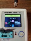
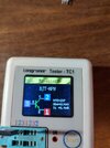
Here are a couple shots of the results when I tested the driver and final in my tester.

Final:
IMG_20240213_092127581_HDR.jpg

Driver:
IMG_20240213_092153933_HDR.jpg


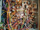
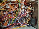
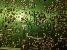
Here are shots of the entire board, topside and bottom.

Bottom:
IMG_20240213_092609047_HDR.jpg

Topside:
IMG_20240213_092656604_HDR.jpg

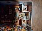
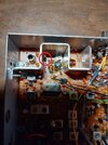
A few more shots:
IMG_20240213_092726904_HDR.jpgIMG_20240213_092803482_HDR.jpg
IMG_20240213_092735744_HDR.jpg
IMG_20240213_092809807_HDR.jpg

Haven't checked the voltages in the transistors mentioned earlier by others, but I will get those for you as soon as I can.
 
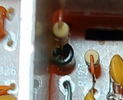
My eyes are not perfect, but it looks like the ferrite bead on R56 might be broke. That keeps the base above RF ground. Without it, not enough RF will get to the final.
bead broke.jpg

bead 2.png
 
  • Like
Reactions: Hawkeye351

dxChat
Help Users
  • No one is chatting at the moment.