I thought I lost all of these models, but apparently I haven't. I'm not sure when I made them, but it is in a folder listed as before 2020 models. One thing I am certain of is it isn't my original imax models meant to test weather a capacitor was present or not, the techniques I used are more advanced than what I used back then, so with these I was likely experimenting with the capacitor's effect on such an antenna.
When it comes to the dimensions and the size and placement of the capacitor that was listed back in 2016, for reference, these are the direct quotes. Thanks again rumblefish and 357 for your work on this, even if it is 6 years late...
The model with the capacitor is using a 42pf cap as listed, and the placement of the cap is within 1 inch of the location quoted by rumblefish, so its very close.
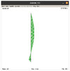
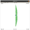
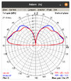
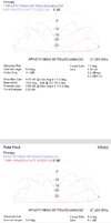
The first image will be the imax antenna current + phase distribution without the capacitor, and the second will be the imax antenna current + phase distribution with the capacitor.
[photo=large]6769[/photo][photo=large]6770[/photo]
In the first image, we see that part of the currents are out of phase with the rest of the antenna, this is typical of a 5/8 wavelength end fed pattern. In the second image we see that none of the currents are out of phase with the rest of the antenna.
At some point I'll sit down and do some more experimenting and playing with these models.
When it comes to the a99 and Imax series antennas, a lot of people like to bash these antennas, and I used to be one of them. But the more I put the design parameters to the test the more respect I have for the designer of these antennas. There are multiple aspects of these two antenna designs that I haven't seen anywhere else when it comes to antennas, and that alone is enough for me to consider these antennas interesting.
The DB
When it comes to the dimensions and the size and placement of the capacitor that was listed back in 2016, for reference, these are the direct quotes. Thanks again rumblefish and 357 for your work on this, even if it is 6 years late...
The cap would be 143 inches away from the top of the antenna.
ok I did more testing and I show 42pf on the middle section
The model with the capacitor is using a 42pf cap as listed, and the placement of the cap is within 1 inch of the location quoted by rumblefish, so its very close.
The first image will be the imax antenna current + phase distribution without the capacitor, and the second will be the imax antenna current + phase distribution with the capacitor.
[photo=large]6769[/photo][photo=large]6770[/photo]
In the first image, we see that part of the currents are out of phase with the rest of the antenna, this is typical of a 5/8 wavelength end fed pattern. In the second image we see that none of the currents are out of phase with the rest of the antenna.
At some point I'll sit down and do some more experimenting and playing with these models.
When it comes to the a99 and Imax series antennas, a lot of people like to bash these antennas, and I used to be one of them. But the more I put the design parameters to the test the more respect I have for the designer of these antennas. There are multiple aspects of these two antenna designs that I haven't seen anywhere else when it comes to antennas, and that alone is enough for me to consider these antennas interesting.
The DB
Last edited:

