• You can now help support WorldwideDX when you shop on Amazon at no additional cost to you! Simply follow this Shop on Amazon link first and a portion of any purchase is sent to WorldwideDX to help with site costs.
  • Click here to find out how to win free radios from Retevis!

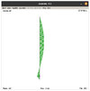
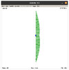
Base Imax Antenna current distribution with and without capacitor

The DB

Sr. Member
Aug 14, 2011
2,054
1,685
193
St. Louis, MO
I thought I lost all of these models, but apparently I haven't. I'm not sure when I made them, but it is in a folder listed as before 2020 models. One thing I am certain of is it isn't my original imax models meant to test weather a capacitor was present or not, the techniques I used are more advanced than what I used back then, so with these I was likely experimenting with the capacitor's effect on such an antenna.

When it comes to the dimensions and the size and placement of the capacitor that was listed back in 2016, for reference, these are the direct quotes. Thanks again rumblefish and 357 for your work on this, even if it is 6 years late...

The cap would be 143 inches away from the top of the antenna.

ok I did more testing and I show 42pf on the middle section

The model with the capacitor is using a 42pf cap as listed, and the placement of the cap is within 1 inch of the location quoted by rumblefish, so its very close.

The first image will be the imax antenna current + phase distribution without the capacitor, and the second will be the imax antenna current + phase distribution with the capacitor.

[photo=large]6769[/photo][photo=large]6770[/photo]

In the first image, we see that part of the currents are out of phase with the rest of the antenna, this is typical of a 5/8 wavelength end fed pattern. In the second image we see that none of the currents are out of phase with the rest of the antenna.

At some point I'll sit down and do some more experimenting and playing with these models.

When it comes to the a99 and Imax series antennas, a lot of people like to bash these antennas, and I used to be one of them. But the more I put the design parameters to the test the more respect I have for the designer of these antennas. There are multiple aspects of these two antenna designs that I haven't seen anywhere else when it comes to antennas, and that alone is enough for me to consider these antennas interesting.


The DB
 
Last edited:

The old way of using pics from albums appears to not work with the forum update, so here are the images above, this time uploaded straight to this message, I think... The first one is the imax without the capacitor, the second one is with said cap.

imaxwithoutcap.jpgimaxwithcap.jpg


The DB
 
I got some of the modeling I want to do done, here is what I have so far.

All of these are models of just the antenna, one in free-space, one at 20 feet above earth, and the last one at 30 feet above earth. None of these have mast or feed line, or any form of ground plane attached, that is something I intend to add later.

First the free-space model.

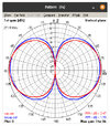
fs-comp.jpg

In this case, the capacitor is making the antenna slightly more efficient (99.57% compared to 99.37%), and has a higher directivity (2.49 compared to 1.98), both of which help it over the non-cap version when it comes to gain.

Another point of note, the version with the capacitor has a 6° angle of peak radiation and a 3dB beam-width of 70° (40° to -30°). The version without the capacitor has a peak gain between 13° and 14°, and a 3dB beam-width of 50° (25° to °-25). This suggests that the version with the capacitor will perform better in local situation, assuming you have absolutely no currents on the mast and feed line, although not so much that you would notice the difference.

Next the 20 foot high models.

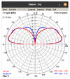
20ft-comp.jpg

When it comes to efficiency, this time the model without the capacitor is more efficient at 57.74% compared to 56.18% for the model with the cap. The model with the cap also has a directivity of 6.08 dB, while the model without the cap has a slightly lower directivity of 6 dB. In this case, the added efficiency of the non-cap antenna noticeably exceeds the gains of the slightly higher directivity of the cap antenna for 0.18 dB more gain.

When it comes to the angle of peak radiation, the non-cap version is slightly lower at 23° compared to the version with the cap at 24°. The version with the cap has a 33° beam-width (39° to 6°) while the version without the cap has a 25° beam-width (39° to 14°).

Finally the 30 foot high models...

30ft-comp.jpg

When it comes to efficiency, again without the capacitor is more efficient at 61.94% compared to 59.52% for the model with the cap. The model with the cap also has a directivity of 6.88 dB, while the model without the cap has a slightly lower directivity of 6.49 dB. These combine to give the antenna with the cap a 0.22 dB high gain.

When it comes to the angle of peak radiation, here they have the same angle of 11°. The version with the cap has a 33° beam-width (39° to 6°) while the version without the cap has a 11° beam-width (5° to 14°).
_____

So, if you look at the data, you will notice that at free-space and 30 feet above the earth the antenna with the capacitor is both more efficient, and has more gain. However, the model at 20 feet neither of those things are true. I'm curious on any thoughts as to why and/or how this happened.
_____

I do intend to make more models that have things like a mast and even two different radial configurations in the future, when I get a chance.


The DB
 
  • Like
Reactions: M0GVZ
DB, EZNEC Pro 2 v6 is now free for everyone. The author has retired and put it up on his website for anyone to download.
 
  • Like
Reactions: The DB
DB, EZNEC Pro 2 v6 is now free for everyone. The author has retired and put it up on his website for anyone to download.
I'm actually aware of this, heard it was coming late last year, and saw it live a few days ago. I will have to see if I can get it running on wine in linux as I don't run windows on my main computer.

I have run tests between 4nec2 and eznec in the past, they produce very close results. The professional version of eznec is more or less the unrestricted version, which 4nec2 never had any of said restrictions in the first place, which is why I used it. I guess he did it that way for making money...

Anyway, I'll check it out when I get a chance, but unless I purchase the nec5 engine, I don't think it will benefit me at all.


The DB
 
  • Like
Reactions: AudioShockwav
Well did you try running the models with radials? What difference did it make if you did? Did you try straight out horizontal radials and downward diagonal 45 degree radials and see a difference?
 
  • Like
Reactions: Marconi
@DB
Perhaps there is additional capacitance to the earth, it being closer to the antenna, that benefits the model... At 30' and free space such capacitance is not influencing the outcome?
Maybe adding a slightly higher value capacitor to the 30' & FS models to see what happens might give insight on this theory?
 
Skyport, I didn't put radials on those models. I'm pretty sure I did at one point just for testing purposes, but I don't recall the results, which generally means that they are underwhelming as if there was a huge difference somewhere I would definitely remember them.

Homer, we are on a similar wavelength. The earth is definitely playing a part in these models and their outcomes. The antennas closer to the earth will definitely be affected by them more, and as you get closer to the earth this effect goes up exponentially. Also the part of the antenna that will be negatively affected by the earth is the bottom part, which is significant when it comes to these models. That being said, I don't think this alone is enough to explain why the 20 foot models has the antenna with the capacitor as the model with the lower gain. For that I need to refer to another observation I have made when it comes to antennas and earths.

This stems from years of modeling experience and the thoughts behind what I have seen when modeling. Essentially, there are some heights that some antenna designs seem to get along with the effect of the earth, while other heights the same antenna designs just seems to suffer. Different designs seem to have different heights that benefit and hinder them. This is an effect separate from and in addition to what we both described above. I think, essentially, at 20 feet of height, the no capacitor design is getting along with the effects of the earth while the capacitor design is being hindered by it, which is partially why we see those results.

I'm sorry if that last part seems vague, its difficult to describe what I see happening without writing a novel length description.


The DB
 
DB, not vague at all.
We've seen other phenomena that defies the general perception of things as they relate to the earth and antenna types.
Notice the overlaid models (thank you, Marconi) of the AP and A99, both 1/2 wave antennas of different types, at 65' upper tip height. The AP clearly has gain advantages at multiple elevations.
Screenshot_20230520_222821_Dropbox-01.jpeg
 
  • Like
Reactions: The DB
Wouldn't the 1/4 wave length ground radials help stop the antennas sensitivity to being low to near the ground?
I watched a youtube video of a guy who measured his Imax 2000 capacitor to be 10 microhenrys
 
capacitor to be 10 microhenrys
Typo? Capacitance is measured in Farads. Inductance in Henrys.
But then again, if it's on YouTube it has to be right..............right?
 
  • Like
Reactions: NZ8N

dxChat
Help Users
  • No one is chatting at the moment.
  • dxBot:
    Greg T has left the room.
  • @ BJ radionut:
    EVAN/Crawdad :love: ...runna pile-up on 6m SSB(y) W4AXW in the air
    +1
  • @ Crawdad:
    One of the few times my tiny station gets heard on 6m!:D
  • @ Galanary:
    anyone out here familiar with the Icom IC-7300 mods