• You can now help support WorldwideDX when you shop on Amazon at no additional cost to you! Simply follow this Shop on Amazon link first and a portion of any purchase is sent to WorldwideDX to help with site costs.
  • Click here to find out how to win free radios from Retevis!

Kenrich Eagle 500-Next Patient

looks like this thread might become the official Kenrich picture depository!

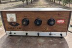
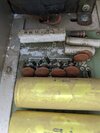
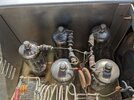
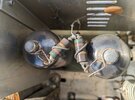
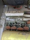
here are my contributions.
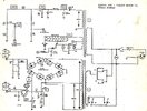
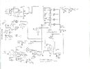
sadly, i think i'm going to have to draw up my own schematic, as unless RVAlleman comes back to the forum, there aren't any for the weird version (eagle VIII) that i have.

View attachment 34488 View attachment 34489 View attachment 34490 View attachment 34491 View attachment 34492 View attachment 34493

LC
Unless one of Ken's kids has a schematic I am not aware of ANY that were publicly released. The only other possibility would be the original engineer who designed for Kenrich, his name is Lon Cecil and the last I heard he was running for governor of NC back in 2016
 
Ken passed September 5, 1998
Heart attack (Seems that the Wellers got the best of him)
Wow glad to see you back on the site.
I was told by a freind of Abe Brewer that Abe suggested to Ken the use 20lf6 on the eagle boxes for increased output. Glad to make the aquaintance of one of the builders of these fine boxes. Did the eagle 500s always use 7 20lf6?
 
Wow glad to see you back on the site.
I was told by a freind of Abe Brewer that Abe suggested to Ken the use 20lf6 on the eagle boxes for increased output. Glad to make the aquaintance of one of the builders of these fine boxes. Did the eagle 500s always use 7 20lf6?
Yes the 500 always used the 20LF6 (2x5), although we only used the tall envelope design which was a proprietary tube. If it didn't have the "Kenrich" logo then it wasn't gonna work to specs. You could always tell when a user was on the air with a Kenrich Amp, one of the most distinct sounds.
There is still a "Kenrich Electronics inc." listed in OKC but I have no idea who the lady is that owns it.
Not sure what brand of tall tubes my eagle has but it will swing up to 800 peak , The spare tubes I have are made in japan tall envelope tubes with the cooling fins on top of the grid. Hopefully they will be close enough if I ever need to use them.
 
The tall tubes were european-made. One way to tell is to look at the glass on top. If the glass has an uninterrupted smooth surface all the way around it was probably from a USA factory. For some reason, european tube manufacturers would fold the top of the glass down to close the top leaving four raised seams visible in the glass around the plate cap. The glass was thicker than the american types, to boot.

Somebody on this side of the Atlantic ocean painted/printed the Ken-Rich brand/logo on the tubes installed at the factory. The story I was told is that the 27LF6 was available in quantity in the early 80s. Went cheap since there were no color TVs sold in the USA that used it for the sweep amplifier. No demand for that number as a repair part. Only european TV receivers ever used this tube. A tube that's available in bulk for cheap is an irresistible incentive if you're building amplifiers with them. But the arithmetic is just all wrong for five times twenty when you put 125 Volts on a five-tube final stage's heaters.

Kinda like a nitrous bottle, but without the "off" switch. Does make the wattmeter incredibly happy.

For a while.

Don't know why, but this, uh, "imbalance" seems to roast the two driver tubes first. Then again, they get their heater supply from a 30-Volt transformer secondary. First hint of this is frequently the plate choke for the two driver tubes when it roasts.

In the late 80s I would get calls looking for the 27LF6 tube. More than one customer had called a supply house and got told "that number isn't on our list". GE stopped showing it on their price lists around 1985, if not sooner.

Sure wish I could remember the european number for it.

There was one other advantage to the original tube. It was designed for use in a TV running from a 240 Volt wall socket.

Not 120 Volts. The insulation between the heater and the tube's cathode in the american-made tube would break down. But the european tubes would not.

This only seemed to happen in the five final tubes. The heater-to cathode RF voltage is added on top of the AC line voltage to ground. Those two voltages add up to a bigger number on the final tubes. The driver tubes have only the radio's RF voltage driving the cathodes. The final stage has the output of the two driver tubes' RF votlage on its cathode. I was told the european tube had to have better insulation so they could operate from twice the wall-outlet voltage.

I remember a few of these amplifiers we saw with a toroid RF choke installed between the two foil pads on the PCB that feed into the five heaters' series string. I don't exactly see how that would help, but it didn't seem to hurt anything.

Had a customer who tracked down his own 27LF6 tubes. Was sharp enough to buy a couple of spares. Good thing, since one tube went "SNAP,flash" under test. Left him one spare that matched the other four finals.

The performance of the glass-factory era base amplifiers depended in a big way on tubes with a perfect quality level. Tubes made in the era of high production-run quantities just had a higher average quality level than tubes made years later in shorter production runs. Might take you ten or twelve late-production tubes to obtain eight tubes that perform like "the old days".

But hey, it's only money.

73
Thanks fo all the info nomad. I think that I will add a small 20 volt transformer to supply the 2 driver tubes and add the resistor to the filament citcuit on the final tubes. The price difference between 2 30kd6 and 2 20lf6 will pay for the transformer. They say if it aint broke dont fix it but I think of this as maintenence.
20lf6 are actualy pretty cheap sometimes, the only people who whant them are guys like me that run kenrich amps
Got 6 0f theese matched 95-100% from a tube dealer for 150.
20220906_055435.jpg
 
Friend of mine keyed up last night, and it's the best he has sound in a long time. He was talking on his Golden Eagle 1K. Keying circuit was acting up on his D&A, and that's the one he uses part of time plus various Elkins.

Anyway, I do remember I ordered him a set of 20LF6 a couple years back, and it was $240 out the door. As soon as he went to high gear, a fuse would pop. We took it to the local amp builder. He use to help Ray build Elkins when he was a teenager. And if I remember right, it came back with two 6KN6 tubes driving four 20LF6.
 
  • Like
Reactions: Enterprise312ok
The files in the folder marked "Ken-Rich" on cb tricks won't load right now.

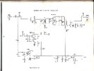
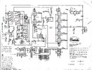
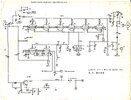
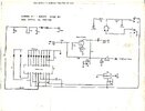
But here are the four that I have. The 150, 500, 750 and 1k.

I know there were production changes, so these diagrams may or not match any single production unit. Should be close, anyway.

73
 

Attachments

  • ge150.jpg
    ge150.jpg
    267.3 KB · Views: 151
  • eagle500s1.jpg
    eagle500s1.jpg
    272.8 KB · Views: 182
  • Ge1kamp.jpg
    Ge1kamp.jpg
    350.7 KB · Views: 150
  • Ge1kmm.jpg
    Ge1kmm.jpg
    282.4 KB · Views: 140
  • Ge1kps.jpg
    Ge1kps.jpg
    251.8 KB · Views: 138
  • goldeneagle750s1.jpg
    goldeneagle750s1.jpg
    274.8 KB · Views: 140
Thanks for all those schematics Nomad. This is the small 20v filament transformer I purchased to supply the driver tubes. It should fit next to the other transformer where the op's unit has an extra fan.
20220912_063242.jpg
 
When I turn my 400 on it all fires up.. just replaced caps... but the choke on the final section is arching ... do you know the value of said choke and what would cause this
My guess would be the high filament voltage, nomadradio suggests changing the 2 drive tubes to 30kd6 To handle the voltage better. I purchased a 20 volt filament transformer. I personally feel like drive level plays a part in that failure. Many people assume that the eagle is high drive on low but it is not.
 
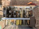
I picked up an old Kenrich Eagle 400 a couple of days ago. I ordered the Kenrich Eagle 515 500 400 Linear Amplifier Refurb Kit HVCAP diodes & Transistors from Ebay. The previous owner told me he still used it right up to the day I purchased it from him.

All the tubes light up and the only thing wrong I can see is a resistor that is falling apart.

Anyone have any ideas or suggestions for me?

Here's some pics:
 

Attachments

  • 1.jpg
    1.jpg
    309.9 KB · Views: 112
  • 2.jpg
    2.jpg
    249.8 KB · Views: 113
  • 3.jpg
    3.jpg
    149.4 KB · Views: 124
  • 4.jpg
    4.jpg
    266.5 KB · Views: 112
  • 5.jpg
    5.jpg
    206.4 KB · Views: 128
  • 6.jpg
    6.jpg
    176.3 KB · Views: 114
  • 7.jpg
    7.jpg
    92.9 KB · Views: 108
  • Like
Reactions: Shadetree Mechanic
Wow! Original tubes. The four raised "seams" on the glass on top of the tube around the plate cap indicate tubes made in europe. That's what the factory was buying in bulk to build this one. American-made tubes have a smooth glass surface surrounding the plate cap.

Clearly the previous owner treated it with respect on the air. For the most part, the factory tubes get abused until they fail.

Good find!

73
Nomad, thank you for helping me understand more about this amp. Have you any recommendations for me? I purchased the refurb kit...is there anything else I should do?
 
  • Like
Reactions: Naysayer

dxChat
Help Users
  • No one is chatting at the moment.