• You can now help support WorldwideDX when you shop on Amazon at no additional cost to you! Simply follow this Shop on Amazon link first and a portion of any purchase is sent to WorldwideDX to help with site costs.
  • Click here to find out how to win free radios from Retevis!

M104C Project

Well, I am slowly but surely making progress. I am making sure to not make this project feel like an unpleasant task so I am taking my time and enjoying other things too. I still need to get the motorcycle out of storage but the weather hasn't been cooperating much lately. It's May 1 and today it is cold and snowing here.

I have a bench mount drill press but had no decent place to keep it. I got tired of moving it around. That sucker is heavy! I knew I was going to need the drill press for multiple things I am doing as part of this project (e.g. making a tilting base plate, anchors, winch plate etc). I had a lot of wood kicking around so I bought a set of casters and built a mobile cart for the press. I already have a 4'x8' table with ramps/casters I built to use for working on snowmobiles, ATV, etc and another 3'x8' with casters I built as a portable work bench. Unfortunately the first version of the drill press table was about 10" too tall so I had to remove this amount from the middle of the legs and sister in shorter legs. Everything is glued and screwed so nothing is going anywhere. It just looks ugly but oh well, at least it's strong and does the job for about $20. Now I could get back to the antenna project.

I have two 12"x12" 1/4" metal plates I am using as the basis for the tilting part. Also two 6" wide metal industrial weld-on hinges that are supposed to each support an 800 pound steel door. I think this should suffice for the weight of the mast, rotor and M104C. The drill press on the new table worked great for drilling the 4 holes I need for the galvanized rods that will be embedded in the concrete.

Oh yes, I also found the right size pipe to use to sleeve the one guy wire anchor pipe. This guy wire pipe is also going to have my youngest daughter's wireless bird feeder camera.

I got the 12' long 2" OD aluminum mast I want to use with the rotor and offset mounts so that's all set.

I completed the mounting plate for the winch. It will be welded between the two heavy duty steel poles that will be used to help raise/lower the mast.

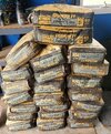
I have brought home 28 60 pound bags of concrete so far. I think I will get another dozen or so to make sure I have enough. I will be renting a portable mixer from Menards and hiring a few neighborhood lads to help with the heavy lifting/mixing. Cheaper than a doctor!

I also found a really good local metal shop for scrap pieces to practice welding as well as use for the real thing. They even gave me a tour of their whole facility. It was a great way to spend my lunch break. I've been back there for more purchases several times since then.

Once the weather improves later this week, the welding will begin. I'm not sure yet if MIG or stick is the way to go. I was told if I go stick to first use a 6011 rod to join the 1/4" metal pieces due to the good penetration then 7018 to basically fill in the rest of the gap. I've done stick welding before but not MIG. I am looking forward to it.

I am getting all of this build stuff out of the way so I can (hopefully) do the concrete, let it set up, then put everything up. I am 100 percent certain it is not going to go this way, but every project needs a goal.

1682950407694.png

Here's the little table's big brother. I've had the ATV, the buggy, snowmobiles, lawn tractor and more on it over the years. Obviously I love to tinker around with things. Cheaper than a therapist my wife says, plus I usually make a little bit of money on these winter projects.

1682950920985.png
1682951145656.png
1682950989663.png
1682950702820.png

1682951040723.png

1682951199323.png
 
  • Like
Reactions: Shadetree Mechanic
The guy wire stuff has arrived and good news. The guy wire ring fits the 2-3/8" mast just fine after I swapped out a bit longer eye bolts. Also, I changed my mind on how I am anchoring the pulley at the bottom. I am going to anchor it in the concrete instead of using a sheave between bottome part of the two poles. I am still using a sheave at the top and a pulley about half-way up the mast. I'm told this should work but I am going to thoroughly test the range of motion with just the mast first to make sure there are no snags raising/lowering the antennae. The winch and pulleys may seem like overkill but 30 feet of schedule 40 2" nominal black pipe, two schedule 40 joint sleeves, a 9 pound rotor, the M104C and V58 do add up. I want to be able to easily raise/lower this setup whenever I want for tuning, experimenting or whatever. Plus the little kid in me is having fun mucking about with all of this stuff.

1683042920687.png
 
I was going to do the concrete for one of the posts today but Mother Nature decided to throw a bunch of rain at us again. Better than the snow she surprised us with on Monday, May 1.

So, I adjourned to the workshop to see if I can come to terms with the new MIG welder and at least get proficient enough to safely weld a few brackets and support pieces together. But first, it was experimentation time with the MIG and stick welder capabilities to see what type of bead I got from various voltages and wire speed on some 1/4" metal pieces I picked up from a local metal shop. While I think I am narrowing in on the best settings for the MIG, I still need to do a lot of practicing with those settings before welding the "real" parts of the setup.

The straight lines on the right are my baselines with what I think are close to what I need. The rest, especially the little section I welded on the left, were just about blowing the puddle right off the welding table. I also did a few passes with a 6011 rod on the stick welder just to see how it penetrated at the higher settings. I think if I turn it down, instead of MIG on the brackets I could also just use the 6011 rod for the first run followed by 7018 to fill it in.

My Dad would shake his head at what I did to this sad, innocent piece of metal. And then teach me what I don't know. Arc welding in high school was a long time ago.

MIGWelding_20230506_143911 - Copy.jpg
 
  • Like
Reactions: Shadetree Mechanic
Mother Nature served up a beautiful day today so I hopped on the opportunity to get the guy wire mount post in place. Five 60 pound bags of concrete and 10 feet of rebar later, it's up and even plumb! Some say to stop the concrete a few inches from the top of the hole and fill with soil but oh well. Other posts I did the same way as this one about 20 years ago for our dogs are still standing proud so it works for me.

I can't put up the twin poles for the winch or the pad for the tilting base until I make some progress on my abysmal welding skills. At least I can do this practice even when it's raining.
 

Attachments

  • GuyWirePost - Copy.jpg
    GuyWirePost - Copy.jpg
    6.5 MB · Views: 11
  • Like
Reactions: Shadetree Mechanic
Time for another update. Progress continues to be made but not always in a straight line.

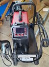
My abysmal welding skills were not being helped by the 20 amp breaker in the workshop in my detached garage tripping every 15 seconds. I needed to run the welder pretty hot because I was working with 1/4" thick metal plate. I talked to a few electricians about getting a 220 volt line installed there and then after I recovered from fainting from the cost, I had a little idea. Hmmm, I thought. I had a 220 volt line ran to a new subpanel in the third bay of the attached garage about 19 years ago for a space heater hanging from the ceiling. It was on a 50 amp breaker. I knew I'd never run the heater and welder at the same time so I decided to install a 220 volt outlet in the single bay of the detached garage where my little workshop used to be and just do any heavier welding in there using that 220 volt outlet. I think it cost me under $100 for the 6 gauge wire, 220 volt receptacle, conduit etc to make it all code legal and poof, I was all set. I resumed my welding training in the old workshop and have not had a breaker trip since then. Of course that immediately moved me on to my next problem of figuring out what pressure to use on the wire feed to stop the bleeping birds nests. Still working on that one. But it did help with the welding, at least I could no longer blame the breaker.

Here's my little ArcCaptain 200 amp friend on a Harbor Freight stand. Nothing fancy but it suits my skill level.

P7 - Copy.jpg

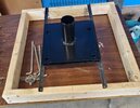
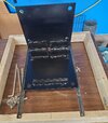
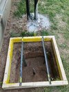
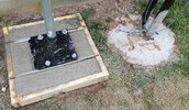
I was able to complete welding the tilting base plate. I used two 12" x 12" x 1/4" plates of steel and two 800 pound capacity each hinges. The welding wasn't the prettiest but it seems quite strong. I also made good use of the the drill press to make the four holes in each plate. I made a little angle iron ledge for it to sit on when the concrete is setting up. The anchor bolts will already be attached loosely to the base so there should be no alignment issues and will be firmly embedded in the concrete.

P2 - Copy.jpg

P3 - Copy.jpg

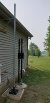
Then it was back to completing building the two 10' long 2" nominal schedule 40 pipes each with an 18 inch sleeved extension to give a bit more height. The two pipes are attached together at the bottom and top by double welded braces and in the middle by the 12" x 12" x 1/4" metal plate that mounts the 2000 pound worm gear winch. The u-bolts are grade 5 so should be plenty strong. I hope! I am doing a bit of experimenting with the pulley setup but I think I've settled on the winch feeding the 1/4" cable down to a pulley at the base that is connected to a 12" long anchor embedded in the concrete footing, then back up to a sheave mounted between the posts nearly 8 feet up the posts, then to a pulley attached to the mast to be raised then the cable finally connects to the top of the post pair. I've seen sailboats with very similar rigging for their gear and figured I'd see how it went. I'm not fully decided yet on how high up to mount the pulley on the mast. I really wanted the posts mounting the winch to be taller than just under 8 feet above ground but this was the best I could achieve with the limitations I had. So far I've just been testing it with the current mast and V58, not yet with the heavier mast, rotor, M104C and V58.

P4 - Copy.jpg
P5 - Copy.jpg

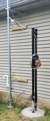
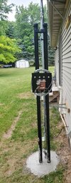
The base for this pair of posts is about 42 inches deep by 18 inch diameter and took 13 60 pound bags of concrete.

I also fixed up some snug sleeves to go at the joints of the new 2" nominal schedule 40 mast. I used 1.5" nominal schedule 40 black steel for the sleeves so I did not have to weld galvanized. I had about 1/5" of a gap to take up so I welded some rings around the sleeves then ground them down so they were a nice tight interference fit and secured them with grade 5 bolts.

P6 - Copy.jpg

I have a bit more fussy stuff to do then I will be taking down the current antenna mast so I can dig the support base hole for the new tilting mast base. I think I'll need about 17 60# bags for it so I have 23 on hand just in case. I think for this step I'm going to rent a mixer. I really hate mixing concrete in a wheelbarrow.

P1 - Copy.jpg
This turned out to be a much bigger project that I thought it'd be but most of that was my choice. A lot of the stuff I could have just ordered from someone on the interweb but what's the fun in that? I'm learning a lot of interesting things along the way including what career I would never want to have (anything to do with concrete).

My goal is the have the beams up by July 1. Or put another 1000 miles on my motorcycle. I know only one of those will happen. :)
 
Last edited:
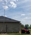
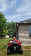
The fun continues. My wife and I were able to take down the Maco V58 and 30' mast last weekend with the only damage to antenna or bodies being a tiny bend in one of the ground plane radials. I won't be re-using them when it goes back up so no problem there.

Early yesterday morning before work I was able to dig the 2' W x 2' L x 2' 6" deep hole for the concrete base. I could have used some type of C4 or other assist to get through was is laughingly called topsoil here. I have a bit of straightening to do on the sides but I am not going to do that until right before the concrete goes in. That was supposed to be this morning but when I went to pick up the concrete mixer from the rental place, the guy that had it yesterday decided to keep it another day so I am SOL. I suppose I could mix the 20 or so 60# bags by hand but I did 13 of them a few weeks ago and that was about 13 too many. Now it is supposed to rain for the next few days so I'm looking at Tuesday before I can try the concrete again. If I can get the mixer. I've been looking for a used one locally to buy but so far no luck.

The tilting base I made out of 1/4" thick steel will sit on the two lengths of angle iron with the J-bolts in place and down in the concrete. There will (should) be about a 1/8" to 3/16" gap between the bottom of the base plate and top of the concrete when I'd done for some levelling room with washers. I figured it'd be easier to the 12" x 5/8" anchor bolts already aligned to the base plate instead of installing the anchor bolts and hope they stay in place. Who knows, this may come back to bit me on the six but it makes sense in my brain.

20230623_075330 - Copy.jpg

20230624_105214 - Copy.jpg
 
  • Like
Reactions: Shadetree Mechanic
I was able to grab a 4 cubic foot concrete mixer last night and went out at 6:30 AM today to do the support base for the tilting mast base. The concrete base is about 24" x 24" x 30" deep and it took 17 of the 60 pound bags of concrete to fill. I was able to mix three bags at a time so it went fairly quickly. I also setup the base plate with the concrete anchors in the required location and used a section of the 2" nominal schedule 40 pipe I am using as a mast to make sure everything lined up correctly. So far, so good. I will let it cure until Friday or so before starting to test the tilt function with the winch using just this single piece of mast. I intend on first testing it on 10 feet of mast, then 20 feet, then 30 feet, then 30 feet with the rotor plate and 12 foot long aluminum antenna mast, then add the rotor, etc. I want this to fail early if it is going to fail. It should be a single man job to raise and lower this mast, at least without the antenna up top. At least that's my goal.

Once I have the 20 or 30 foot sections of mast in place, I will also be able to establish the height and orientation of the three guy wires I plan on using. Two of the anchors will screw into the rafters through the roof. I am getting some expert advice on how to do this without it leading to leaks in the roof. I intend on doing this into the rafters in the soffits instead of over interior parts of the house because then if it does end up leaking, at least it's leaking outside.
 

Attachments

  • 20230627_101306 - Copy.jpg
    20230627_101306 - Copy.jpg
    3 MB · Views: 5
  • 20230627_101225 - Copy.jpg
    20230627_101225 - Copy.jpg
    1.3 MB · Views: 5
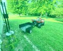
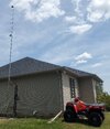
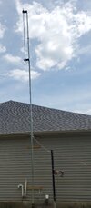
I finished some of the fussy prep-work and was able to begin testing the various contraptions this morning. Overall I am satisfied with the results so far but I do have a few niggling concerns. I did decide to use the winch from my ATV as a counterbalance to the poles with the worm gear winch on them. The two poles are set in more than 3.5 feet of concrete with 13 bags holding them in placed. But still, I saw a bit more deflection than I liked during the testing so far so I figured better safe than sorry. I did try to screw in two 3 foot long anchors and was going to run some cable from them to the top of each of the two poles for this support but the ground is too hard to do that.

I have not tried it with the rotor in place yet. I should be able to get to that tomorrow. I sure do hope these three 10 foot sections of 2" nominal schedule 40 pipe with a two foot length of 1.5" schedule 40 pipe sleeve at each of the two spots where the pipes join will be strong enough. I may see what I can find to use as an outer support/sleeve at the lower junction point. The upper junction point just happens to fall under the bottom bracket where the rotor will be at the 20 foot level. The 12' long aluminum mast will extend a foot or so past the top of the schedule 40 pipe and will have the Maco M104C mounted horizontally then the V58 a foot or so above that. Right now I have the guy wire ring at the 25' level. Not sure it that's where it will end up. I will decide that in a bit.

It sure is nice to be able to raise and lower this by myself using nothing more than a cordless drill and a 5/8" deep socket. When I raise it with both antennae and rotor installed I may have a friend up on the roof pulling a bit on a rope attached to the mast just to give the system a bit of extra help in the first bit of cable travel where a lot of winch force is pulling the mast toward the base instead of up. It would have been better to have taller posts holding the winch but this "could have / should have" just never ends.

I should have just had an electrician pull some permits and get the electrical service moved so I could have used the tower. Of well. Once this is up and guyed it should be very secure. Famous final words for $100, Alex.

1 - Copy.jpg2 - Copy.jpg3 - Copy.jpg4 - Copy.jpg5 - Copy.jpg
 
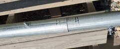
This is the joint I am looking at for additional strengthening with some type of outer sleeve (or maybe a really, really strong plaster cast. ;) ) It's the one connecting the bottom and middle sections of 10' long, 2" nominal schedule 40 pipe. The bolts in the picture hold a two foot length of 1.5" nominal schedule 40 pipe inside as a strengthening sleeve. The gap between the OD of the 1.5" nominal and ID of the 2" nominal was taken up by multiple beads welded around the circumference of the sleeve.

I'm reluctant to weld anything to this galvanized pipe after being told how dangerous the fumes can be.

20230630_140007 - Copy.jpg
 
  • Like
Reactions: Shadetree Mechanic
This is the joint I am looking at for additional strengthening with some type of outer sleeve (or maybe a really, really strong plaster cast. ;) ) It's the one connecting the bottom and middle sections of 10' long, 2" nominal schedule 40 pipe. The bolts in the picture hold a two foot length of 1.5" nominal schedule 40 pipe inside as a strengthening sleeve. The gap between the OD of the 1.5" nominal and ID of the 2" nominal was taken up by multiple beads welded around the circumference of the sleeve.

I'm reluctant to weld anything to this galvanized pipe after being told how dangerous the fumes can be.

View attachment 64415
Although welding galvanized is potentially dangerous, as long as you are outside it should not be a problem. You can see the pink smoke it makes, just stay to the side so it doesn't go in your welding helmet. That being said, I don't think welding it would make it much stronger. The pipe inside and outside would both have to deform for it to bend, I would think that the weak point would be at the ends of the inside pipe where it goes from two pipes to one pipe. Or I could be totally wrong, but that's what comes to mind.
 
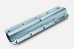
I'm thinking of something like this mast sleeve but one that will fit a 2-3/8" pipe. If I had an acetelyene torch I may be able to make one out of 1/8" steel but all I have is a little propane torch. Might be time to put on my McGyver hat again and go rummaging through the "scrap metal and stuff" boxes in the shop and see what turns up.

1688319748032.png
 
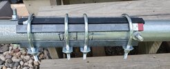
Some 1/4" x 3/4" flat bars and two pieces of 3/16" x 3/4" angle iron and some 3/8" clamps. Good enough. I winched up the mast and it seems to have helped. I'll at least prime the bare metal pieces before this goes up for good.

ShouldHoldIt.jpg
 

dxChat
Help Users
  • No one is chatting at the moment.