You are using an out of date browser. It may not display this or other websites correctly.
You should upgrade or use an alternative browser.
You should upgrade or use an alternative browser.
-
You can now help support WorldwideDX when you shop on Amazon at no additional cost to you! Simply follow this Shop on Amazon link first and a portion of any purchase is sent to WorldwideDX to help with site costs.
need help with frequency
- Thread starter 1iwilly
- Start date
As crystals age they can change from the frequency they were cut for, usually not a lot but enough to account for the difference between a digital radio vs. a radio made in the 70's, if that's what you're asking about (if I read it correctly). Also, if I recall correctly, there were even differences between various crystal synthesized radios, like the CBs made in the 70's. Each had a set of mixing crystals to get to the correct channel(s). Usually 1 mixing crystal gave you 4 channels. So if you had a 23ch CB where suddenly a block of channels stopped working (i.e. ch1-4) it would very possibly be the mixing crystal for that block. Different manufacturers designed different radios, often using different crystals frequencies to get to the same channel and another set. If this isn't the info you wanted, disregard.
thanksAs crystals age they can change from the frequency they were cut for, usually not a lot but enough to account for the difference between a digital radio vs. a radio made in the 70's, if that's what you're asking about (if I read it correctly). Also, if I recall correctly, there were even differences between various crystal synthesized radios, like the CBs made in the 70's. Each had a set of mixing crystals to get to the correct channel(s). Usually 1 mixing crystal gave you 4 channels. So if you had a 23ch CB where suddenly a block of channels stopped working (i.e. ch1-4) it would very possibly be the mixing crystal for that block. Different manufacturers designed different radios, often using different crystals frequencies to get to the same channel and another set. If this isn't the info you wanted, disregard.
Not sure I know what you mean by "input frequency". Generally speaking the displayed frequency on the radio is the carrier frequency, even if you're on SSB. There are lots of things that can make your 70's radio be off frequency and Woody hit on some of them. Main thing is if you want to be sure you're on the right TX frequency, you need a decent frequency counter, or at least a radio that you are confident is on frequency (test radio). If you have a frequency counter use a sampling coupler to connect your radio under test (RUT) to a dummy load and connect the sample port to the counter. Then, make sure that the output level of the coupler is withint the normal range for the counter, and if it is, transmit into the dummy load and read the frequency. The sampling coupler is because you have a nearly 100% chance of overloading and destroying parts in the counter if you TX directly into it. If you don't have a counter, use a different radio (test radio) that you are confident is on frequency. Do NOT connect anything to the antenna port of the test radio. Connect the radio under test to a dummy load and turn the output power all the way down. Set both the test radio and the radio being tested to the same frequency. Put the radio under test in AM mode, and the test radio in SSB. Then transmit into the dummy load with the radio under test, turning up the power only if you can't hear the signal in the test radio. Most likely you will even on lowest power. Once you can hear the signal on the test radio, zero beat it. Then read the frequency from the test receiver. This is your carrier frequency on the radio under test.
I hope that helps!
I hope that helps!
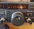
What you really are asking for is the frequency shown on an external "Display" (while on SSB) of the FT-101E radio being different than as (you call it) a Digital Radio (a radio with a built-in Display).i'm looking for help or guidance to understand better how to figure out the actual input frequency. example
on digital radio 27.3850 but on crystal radio ft-101e it's 27.3830
on 40 meters digital 7.27200 on ft-101e 7.2686 give and take a digit
Every AM radio has two sidebands while transmitting, one on either side of the AM carrier (USB and LSB), but the SSB radio actually can use them.
You have to understand that the frequency shown by the radio is just a "Display", even the "Digital" radio is a Display.
The only time you call it a "Frequency Counter" is when you are using it to make adjustments in the radio, or externally sampling the RF going to the antenna, and the Display has to read the same as the frequency counter while transmitting on AM.
The actual frequency that the Display uses comes from the VCO, (or VFO) which then has an "offset number" added to it in code for the Display to read the output frequency. (There is another way by mixing different internal frequencies of the radio and code to display it.)
Since the Display is programmable by the code that runs it, why not make it easier for the operator to read the AM frequency? This way if your radio is calibrated properly you can hear others that are not on frequency.
If the CB radio has a built-in Display, when adjusting the synthesizer circuit the VCO frequency and Oscillator frequency adjustments have to be made with a frequency counter. AM, LSB, and USB settings are different for the radio, but the "Display" will show the AM frequency due to the design of the code.
There are external displays sold that can be added to CB radios (and also for specific older ham radios), some had wires that connected to the USB and LSB circuit so that the radio Displayed the AM frequency, others did not, and some just had a plug to plug into the back of the radio.
You already saw it yourself on the FT-101E. In reality, all SSB radios have an offset actual frequency that the radio is on, but the "Display" disguises it to read the AM frequency.
I hope this clears things up, and why the synthesizer adjustment is critical to all radios. A locked clarifier radio on SSB ....... will hear it all day "Get on Frequency!"
73
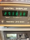
OK This is what i meant Look at the pic i waited until i got my ft-101e back from having it fully aligned with digital radio freq ends in 50 This is for SSB only on yaesu 101e The receive and transmit for lsb=27.3830 and USB= 27.3860 all figured out once i got the yc-601
Attachments
Are you recalibrating your dial when going from AM to SSB? Check out page 10 of the instruction manual:

It looks like the VFO does the same thing no matter what mode you select. In other words, changing from AM to SSB does nothing to the VFO output (the thing with the vernier dial, unfortunately). It is the job of the individual oscillators on the mod/osc board to shift the frequency for SSB. Because of that, the vernier dial needs to be adjusted for each mode. When you got it tuned up at the shop, the dial was probably calibrated in AM. That same page explains how to calibrate it when switching modes.
In support of this theory, the digital display you have operates on that same VFO signal (that needs to be recalibrated for the mode change). There is a frequency counter option for the FT101 that samples the RF output, but the display you have samples the VFO output instead. So if the VFO vernier scale has not been recalibrated for the mode change, I could see that being an issue.
That counter reads ONLY the VFO frequency.
But the VFO gets mixed with one of three carrier crystals to match the selected mode. That's one of two reasons for the calibrate knob. This lets you move the reading up or down the opposite amount the carrier crystal moves your frequency when changing modes.
The SECOND source of error is the band-select or "HFO" crystal. They are usually within a couple of kHz of what's marked on them. Likewise, that calibrate knob will compensate for this when changing bands.
But this display is only correct when you calibrate it again every time you change band or mode. It will only be valid this way, and changing band or mode will instantly introduce some error in what's displayed.
73


