• You can now help support WorldwideDX when you shop on Amazon at no additional cost to you! Simply follow this Shop on Amazon link first and a portion of any purchase is sent to WorldwideDX to help with site costs.
  • Click here to find out how to win free radios from Retevis!

Siltronics LA-550 " keying relay issues"

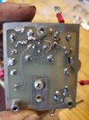
You need to use diode test mode, to properly bias the device. Continuity test is not valid. You should have around .6 volts forward from B-C and B-E in one direction. Reverse should be zero volts. C-E might have some leakage normally, might not. It depends of the
You need to use diode test mode, to properly bias the device. Continuity test is not valid. You should have around .6 volts forward from B-C and B-E in one direction. Reverse should be zero volts. C-E might have some leakage normally, might not. It depends of the device. I would remove both. clean the board, repair the burned/missing traces first. The 2SC945 is not a drop in replacement. Electrically it is similar. However, you will need to reverse the base and collector. With the flat side of the device facing you, The pinout of the 2N5419 is EBC. The 2SC945 is ECB.
I got the transistors replaced and it is still not engaging unfortunately, is there a way to test one of the wires sending the signal to the relay or something I can check there ?

The canister is a transistor. I would check it, replace if necessary and clean up the traces/pcb.

SL
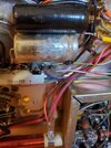
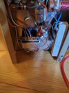
Hi, I have been working on this quit a bit trying to figure out what is going on with it, there is a green and yellow wire that runs to the bypass, low, and high power switch and it shows in the schematic that this wire should have 16v and it has hardly anything at all, I also check the 250 uf 20v capacitor and I am not getting anything there either, could the diode coming from the yellow power supply wire be bad or ??? There is also a red white and purple wire on that lug that goes down to this little transformer on the bottom here but I am only getting a gound on it also, it seems everything on that lug is showing a Gnd when it should be 16 VDC
 

Attachments

  • 20221028_191159.jpg
    20221028_191159.jpg
    1.6 MB · Views: 86
You need to use diode test mode, to properly bias the device. Continuity test is not valid. You should have around .6 volts forward from B-C and B-E in one direction. Reverse should be zero volts. C-E might have some leakage normally, might not. It depends of the
You need to use diode test mode, to properly bias the device. Continuity test is not valid. You should have around .6 volts forward from B-C and B-E in one direction. Reverse should be zero volts. C-E might have some leakage normally, might not. It depends of the device. I would remove both. clean the board, repair the burned/missing traces first. The 2SC945 is not a drop in replacement. Electrically it is similar. However, you will need to reverse the base and collector. With the flat side of the device facing you, The pinout of the 2N5419 is EBC. The 2SC945 is ECB.
I got the transistors replaced and it is still not engaging unfortunately, is there a way to test one of the wires sending the signal to the relay or something I can check there ?

The canister is a transistor. I would check it, replace if necessary and clean up the traces/pcb.

SL
Hi, I have been working on this quit a bit trying to figure out what is going on with it, there is a green and yellow wire that runs to the bypass, low, and high power switch and it shows in the schematic that this wire should have 16v and it has hardly anything at all, I also check the 250 uf 20v capacitor and I am not getting anything there either, could the diode coming from the yellow power supply wire be bad or ??? There is also a red white and purple wire on that lug that goes down to this little transformer on the bottom here but I am only getting a gound on it also, it seems everything on that lug is showing a Gnd when it should be 16 VDC
Screenshot_20221029-151422_Photos.jpg20221029_151856.jpg
 
Hi, I have been working on this quit a bit trying to figure out what is going on with it, there is a green and yellow wire that runs to the bypass, low, and high power switch and it shows in the schematic that this wire should have 16v and it has hardly anything at all, I also check the 250 uf 20v capacitor and I am not getting anything there either, could the diode coming from the yellow power supply wire be bad or ??? There is also a red white and purple wire on that lug that goes down to this little transformer on the bottom here but I am only getting a gound on it also, it seems everything on that lug is showing a Gnd when it should be 16 VDC

View attachment 61064View attachment 61065
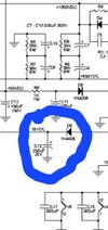
If your lamp is on and tube filaments are lit, that power supply is working. You will see 16VDC at the cathode of D5. If you don't, then check D5 and C13. If none of the above are what you are finding, no lamp, no filament, then check black and yellow/black at T1 for 13VAC. Also, the RF sense relay is only active with the bypass/low/high switch, in low or high. If you see the 16VDC in bypass, but not high or low, then I am going to guess, your transistors on the keying board are not correctly installed. You can't take for granted, that someone had them oriented correctly when you took possession of this amp. You will need to follow the schematic and verify the correct orientation of the two devices. More so, if you used 2SC945's.

SL
 
Last edited:
If your lamp is on and tube filaments are lit, that power supply is working. You will see 16VDC at the cathode of D5. If you don't, then check D5 and C13. If none of the above are what you are finding, no lamp, no filament, then check black and yellow/black at T1 for 13VAC. Also, the RF sense relay is only active with the bypass/low/high switch, in low or high. If you see the 16VDC in bypass, but not high or low, then I am going to guess, your transistors on the keying board are not correctly installed. You can't take for granted, that someone had them oriented correctly when you took possession of this amp. You will need to follow the schematic and verify the correct orientation of the two devices. More so, if you used 2SC945's.

SL
Yes sir I will check everything mentioned above, but what I meant is I never see 16 volts in that yellow/green white wire at all even with the switch on low or high even if I key up. The power supply or coil I was referring to is very little not the large power supply. I believe I installed the transistors correctly but mistakes do happen 16670758672684340682430613024604.jpgThanks again !
 
If your lamp is on and tube filaments are lit, that power supply is working. You will see 16VDC at the cathode of D5. If you don't, then check D5 and C13. If none of the above are what you are finding, no lamp, no filament, then check black and yellow/black at T1 for 13VAC. Also, the RF sense relay is only active with the bypass/low/high switch, in low or high. If you see the 16VDC in bypass, but not high or low, then I am going to guess, your transistors on the keying board are not correctly installed. You can't take for granted, that someone had them oriented correctly when you took possession of this amp. You will need to follow the schematic and verify the correct orientation of the two devices. More so, if you used 2SC945's.

SL
I was testing wires at that keying relay while I was trying to key up and the only wire I had any power to speak of really was the larger orange one which had 24 VDC in it at all times, none of the other wires had anymore than 1v
 
I was testing wires at that keying relay while I was trying to key up and the only wire I had any power to speak of really was the larger orange one which had 24 VDC in it at all times, none of the other wires had anymore than 1v
Are the tubes lit? Lamp? Check what I told you earlier! What do you see at the cathode of D6? If zero, lift the cathode and see what's there. If 16VDC you have something shorted beyond that diode. Check C13 for short. I think this is as far as I can go without actually repairing it myself!

SL
 
If your lamp is on and tube filaments are lit, that power supply is working. You will see 16VDC at the cathode of D5. If you don't, then check D5 and C13. If none of the above are what you are finding, no lamp, no filament, then check black and yellow/black at T1 for 13VAC. Also, the RF sense relay is only active with the bypass/low/high switch, in low or high. If you see the 16VDC in bypass, but not high or low, then I am going to guess, your transistors on the keying board are not correctly installed. You can't take for granted, that someone had them oriented correctly when you took possession of this amp. You will need to follow the schematic and verify the correct orientation of the two devices. More so, if you

Are the tubes lit? Lamp? Check what I told you earlier! What do you see at the cathode of D6? If zero, lift the cathode and see what's there. If 16VDC you have something shorted beyond that diode. Check C13 for short. I think this is as far as I can go without actually repairing it myself!

SL
Absolutely, I will check all this, and yes the power lamp and all the tubes are lit but the driver tube sounds like it is buzzing a bit
 
Absolutely, I will check all this, and yes the power lamp and all the tubes are lit but the driver tube sounds like it is buzzing a bit
You mentioned changing tubes, to a tube that has 6 volt filament. Is the driver tube still the 8950? Or did you change that to a 6 volt tube as well? If you changed all tubes to 6 volt, this will not work. You need an even number of tubes to series/parallel 6 volt tubes in a 12 volt circuit. If you are trying to light 5 tubes, you will need a new 6 volt supply for the filaments.
 
You mentioned changing tubes, to a tube that has 6 volt filament. Is the driver tube still the 8950? Or did you change that to a 6 volt tube as well? If you changed all tubes to 6 volt, this will not work. You need an even number of tubes to series/parallel 6 volt tubes in a 12 volt circuit. If you are trying to light 5 tubes, you will need a new 6 volt supply for the filaments.
Yeah, the driver tube is still a 8950
 
The 8950 is buzzing though and doesn't seem quite right to me, there is also a slight bit of blue coloring in it at top and bottom , I have tried 2 different 8950 and both did it i have a feeling somthing is shorted out in this amp causing both issues but I could be wrong too, I have to work this morning but will do the testing that you mentioned above later today
 
The 8950 is buzzing though and doesn't seem quite right to me, there is also a slight bit of blue coloring in it at top and bottom , I have tried 2 different 8950 and both did it i have a feeling somthing is shorted out in this amp causing both issues but I could be wrong too, I have to work this morning but will do the testing that you mentioned above later today
Blue tubes like that are typically gassy, but not always. You need to check the voltages with the tubes uninstalled.
 
Blue tubes like that are typically gassy, but not always. You need to check the voltages with the tubes uninstalled.
Hi, here are my findings I checked the cathode at D6 with all tubes removed and the most I saw was 2 volts dc and it would quickly drop off to nothing, so I lifted the cathode side and checked the cathode side again and still had nothing, I also checked the spot where the cathode was soldered to and the large yellow wire coming from the large power supply and had nothing there also, I might also add that the buzzing sound must be coming from the power supply and when I lifted the diodes cathode the buzzing had stopped ! Thank you for your help I really appreciate it !
 
I also then tried to check C13 for a short but I am not positive on how to do that I am sure I can look it up, it did not beep on continuity on my ohm meter but it did show 259 ohms ?
 
I also then tried to check C13 for a short but I am not positive on how to do that I am sure I can look it up, it did not beep on continuity on my ohm meter but it did show 259 ohms ?
Check the voltage at the lifted cathode of D6 to ground. Both AC and DC voltages. Then do the same at the anode. What do you see there?
 

dxChat
Help Users
  • No one is chatting at the moment.
  • @ Crawdad:
    One of the few times my tiny station gets heard on 6m!:D
  • @ Galanary:
    anyone out here familiar with the Icom IC-7300 mods
  • @ Crawdad:
    7300 very nice radio, what's to hack?
  • @ kopcicle:
    The mobile version of this site just pisses me off
  • @ unit_399:
    better to be pissed off than pissed on.