• You can now help support WorldwideDX when you shop on Amazon at no additional cost to you! Simply follow this Shop on Amazon link first and a portion of any purchase is sent to WorldwideDX to help with site costs.
  • Click here to find out how to win free radios from Retevis!

Siltronics LA-550 " keying relay issues"

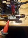
I used the 2NC945 I had to twist one around pretty good but it worked out ok but no I have not checked them since the install, but sitting here on break I am thinking about something that I may have done incorrectly, there is a large resistor on that relay board on the bottom and it goes down to antenna in jack, I am wondering if that was supposed to go to ground instead of the center post ????
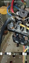
That one down at the bottom left, where is it actually supposed to go ? Screenshot_20221031-092550_Gallery.jpg
 
I used the 2NC945 I had to twist one around pretty good but it worked out ok but no I have not checked them since the install, but sitting here on break I am thinking about something that I may have done incorrectly, there is a large resistor on that relay board on the bottom and it goes down to antenna in jack, I am wondering if that was supposed to go to ground instead of the center post ????
It broke off the antenna connector when I was originally removing the board and it had looked like it was soldered to the center stud by the way the solder looked right there when it came off but whoever worked on it before I am wondering if they soldered that to the wrong spot but I ended up putting it back on there not really thinking about that at the time
 
I used the 2NC945 I had to twist one around pretty good but it worked out ok but no I have not checked them since the install, but sitting here on break I am thinking about something that I may have done incorrectly, there is a large resistor on that relay board on the bottom and it goes down to antenna in jack, I am wondering if that was supposed to go to ground instead of the center post ????
Refer to your schematic. R29
 
  • Like
Reactions: Danzik
I guess now that I am home and see the schematic it is a capacitor, so I will probably be testing that one

So, it's a 2 watt 10,000 ohm resistor, and it does look like it goes to the center of the output coax
No it doesn't. Look at the schematic.... Junction of K1/L9/C42/L8....other side to junction of R32/D9 anode. Where are you from?
 
  • Like
Reactions: Danzik
No it doesn't. Look at the schematic.... Junction of K1/L9/C42/L8....other side to junction of R32/D9 anode. Where are you from?
I am trying to understand this as it looks like it would connect to the coax coming from the plate and load controls where it connects to the relays circuit ? But that other little schematic that has D9 on it has me confused, so this is on the bottom of the amp probably around where I replaced D5 and D6 I would assume
 
No it doesn't. Look at the schematic.... Junction of K1/L9/C42/L8....other side to junction of R32/D9 anode. Where are you from?
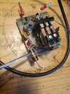
I admit, I am confused you do know I am referring to the one mounted on the keying relay correct? 16672447624902216929489150405621.jpg
 
I admit, I am confused you do know I am referring to the one mounted on the keying

I admit, I am confused you do know I am referring to the one mounted on the keying relay correct? View attachment 61087
I am trying to understand this as it looks like it would connect to the coax coming from the plate and load controls where it connects to the relays circuit ? But that other little schematic that has D9 on it has me confused, so this is on the bottom of the amp probably around where I replaced D5 and D6 I would assume
I see it I just dont understand why they broke up the schematic of the actual relay circuit board where it is in two different places and trying to view it on a phone is not the easiest as I should have printed it out, the purple wire out goes to the meter and it looks as if the resistor is supposed to hook to the coax coming from the plate and load controls but if it does the previous person removed a wire or somehow turned that 2 w resistor the other direction ‍♂️
 
Check your schematic again when you get the chance. That resistor does not connect to the center pin of the output S0-239 connector. (FYI The center pin of the output S0-239 connector attaches to the "Common" terminal of the relay. "Common" meaning it is involved weather the relay is energized-in which case it will connect to the Normally Open terminal-or if it is not energized-where it will connect with the "Normally Closed" terminal)

It appears that R29 (your 10,000 ohm 2 watt resistor) feeds the relative output metering circuit.
One end is attached to the normally open contact of the relay (along with L9 a 30uH choke).
The other end is connected to the junction of R32(a 470 Ohm resistor-yellow/violet/brown), D9(a 1N60 Diode connected to the unbanded end), R31( a 4700 ohm resistor-yellow/violet/red) and C479(a .01 uF ceramic capacitor)

I believe the variable resistor @nomadradio mentioned in an earlier post (VR4/10k) either sets the amount of delay when in the SSB mode or "dials in" the amount of RF power it takes to key the amplifier.

Good luck. Stick with it. You are doing fine.

73
David
 
Danzik,
Think of the schematic showing two different systems.

One is the flow of RF. The path your transmitted signal follows when barefoot or on "Standby" and when "Hammer Down" or in the "Operate" mode. Your RF does not flow through the filament circuit of the tubes nor does it flow through the coil of the relay.

The other "system" would include:
- the power transformer. Don't get RF through there but it is necessary for the amplifier to amplify
-the relay(s) coils. No RF flowing there*
-Tube filament voltage flow, fan power (if equipped), meter light bulbs, pilot lights, pre-amp relay controls, switches etc.


* A small bit of RF is "siphoned off" by C43 (a 10 picofarad capacitor) and rectified to a very small DC voltage by D7 and applied to the base of Q1 to provide part of the RF keying circuit.

Don't stress. We are here to help.

73
David
 
  • Like
Reactions: Danzik

dxChat
Help Users
  • No one is chatting at the moment.
  • @ BJ radionut:
    EVAN/Crawdad :love: ...runna pile-up on 6m SSB(y) W4AXW in the air
    +1
  • @ Crawdad:
    One of the few times my tiny station gets heard on 6m!:D
  • @ Galanary:
    anyone out here familiar with the Icom IC-7300 mods
  • @ Crawdad:
    7300 very nice radio, what's to hack?
  • @ kopcicle:
    The mobile version of this site just pisses me off