• You can now help support WorldwideDX when you shop on Amazon at no additional cost to you! Simply follow this Shop on Amazon link first and a portion of any purchase is sent to WorldwideDX to help with site costs.
  • Click here to find out how to win free radios from Retevis!

uniden pc 66 XL no power

Read Thru...

No 5volts going into pin 1 of ic3

R84 takes power from Q17 - check for ~ 9 Volts on side that goes towards VR2.
IF you get 9 V or thereabout's means Q17 is working...
Measure R84, ohmic 47 ohms but it's a 1/6th W see if it blew open.
See My Post above - Zener D13 is this sections 5V regulator C104 is also suspect due to age.
C103 another one that pulls voltage out of this area.

THE CASE IS insulated electrically for POSITIVE OR NEGATIVE GROUND - so it is not the place to ground your test leads - use L1 or and shield can that FOIL BOARD ground
Regards!
:+> Andy <+:
 
What is the voltage (check both resistor leads - on VR2 side and PLL side measured to ground for voltage) on R84 when the radio's powered up?

IF 0V - then check Q17 ...

You might want to try continuity checks for popped traces...

Lots of good stuff in those early posts...

:+> Andy <+:
 
bad voltage regulator. That radio has 2 or 3 of them.

Here is what i found so far i use my multimeter i get negative reading on my voltmeter, could be short anywhere maybe?

Remember that this radio is an INSULATED chassis - RF passes, but blocks DC to 4.7K resistance / impedance - so used board ground or tap onto the NEGATIVE power in power cord terminal on that uniden 3pin.

sorry I have to stop answering these posts when I'm tired I was thinking pc78

No don't!

You are correct, there are two on the 66 and 68 series,
no problems - nice ride!

Good to hear from you...
 
Thanks Andy.... I was thinking the one that screws to the chessie behind the encoder and the one that sticksup along the side near the Mic socket. But I was thinking of the wrong radio.
 
Well, "gold side" doesn't help much, but I presume that no matter the reading - you're still flat. Meaning - something further back towards the input is bad.

Either way, PLL out because of no voltage.

You said you get a meter light?

Better look further back towards the power supply filter choke.
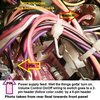
PC66Powerrouting.jpg

But wait - theres more.

The age of the radio - check the power switch ON/OFF Volume - see if it even shows continuity when "clicked" on.

PC66XLONOFFVOLUMEPower.jpg PC66PowerFOilSide.jpg


Power from switch then heads back to the board via that 2-pin header for distribution - Q17 the power regulator - note the TO-92 GIANT case - so look for something that can handle at least 1 amp continuous if replacing Q17. C118 is also a smoothing filter cap from this area and this is what branches off to feed R84.

Hope this helps!
Regards!
:+> Andy <+:
 
power switch works with continuty tester,when i put continuity tester on those 2 pins and turn switch on and off i get nothing.nothing comes on in front panel no leds come on or channel display whole front of the radio is out also meter light is out as well.
 
Last edited:
Start continuity checks from Power Choke on up - including Uniden Connector -look for "popped" traces - sounds like a catastrophic failure - including the Power protection diode. Locate D17 by 3.9 Ohm speaker "ballast" resistor by Uniden Power connector and PA and EXT spkr jacks.

PC66PowerInputSection.jpg

I would not be surprised if the downlead power choke / bead torroid thingy - blew open - popped - like a fuse.

Foil side as well...look for popped traces...
PC66PowrInputFoil.jpg

Just about anything is suspect - so hope for the best and expect the worst.

Wanted to pass this along, YOU MAY SEE THE UNIDEN POWER CONNECTOR is installed, but is it oriented correctly in the SOCKET - CUTOUT on the rear panel?

I've come across Uniden connectors installed so that the NEGATIVE lead is backwards to the stamped on the package - they don't have a keyway for the jack itself when it's installed, only for the PLUG and it's MATE connector - so you've been warned. It means that this connector can be installed reversed and wired as stamped on chassis - but to insert the plug it goes in "proper" polarity oriented but the power wiring is also reversed internally - reversing polarity because the connector jack is in backwards. not many catch that.

I've seen kids put perfectly good radios up as junk, smoked them because of the reversed power orientation leads INSIDE because they didn't pay attention - so be prepared.

Regards!
:+> Andy <+:
 
Not sure if this is what you want but - here goes...

Powerconnector.jpg

Note the Pin out - following + POWER - but note the keyed "bevel" only for the power cord into jack, not the cutout of the chassis to mount the jack itself - seen this wired where the 2 pins closest to each other were on the Plus " + " side and the radio D17 and traces to Power Choke blown - referring to above message - the user would think that NEGATIVE was closer to side panel while positive was towards the antenna jack - then wired up internally never knowing the bevel forced the user to rotate the cord to fit - reversed.

Regards!
:+> Andy <+:
 
  • Like
Reactions: kaos513

dxChat
Help Users
  • No one is chatting at the moment.