You are using an out of date browser. It may not display this or other websites correctly.
You should upgrade or use an alternative browser.
You should upgrade or use an alternative browser.
-
You can now help support WorldwideDX when you shop on Amazon at no additional cost to you! Simply follow this Shop on Amazon link first and a portion of any purchase is sent to WorldwideDX to help with site costs.
Mixer IC I think
- Thread starter Smokinone
- Start date
I'll take some measurements in the morning on the pins at the bottom of the PLL "can" and see whats up. If I'm not getting the 10.240 at the PLL it may be bad. I can read 10.240 at the X-tal itself tho
I have all the channel selector leads apart as the wires and insulation have broke down and broke.
I don't believe the list of applicable radios in that sardine pdf are accurate.OK, I just found some more information on the PLL section "sardine can" PLL. I will have a look at it later and take some measurements.
Here's what I have from my book.
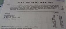
For example, the 641 uses pin 1 (38MHz), pin 12 (10.24MHz AM, 11.15MHz SSB) and pin 15 (455kHz).
The PLL unit for the 621 uses pin 2 (10.24MHz), pin 19 (37MHz) and pin 23 (27MHz).
And then there is your PLL which uses pin 1 (10.24MHz), pin 11 (17MHz) and pin 14 (27MHz).
That pdf shows all your output pins as ground pins.
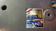
On the bottom of the sardine can on this unit are 14 pins, unlike the 24 in the previous diagram.
On those, 3 and 8 have 6.47, and 9, 10, 12 have 12V. That's reading from the back of the board forward. Or the top down i the pic.

I also took a voltage reading on Q401 (2SC1096), which is the voltage regulator and I have 12 V on the 2 outside legs, and 5V on the middle leg as it sits in the board. It' supposed to be, according to the schematic, 12V 9V and 9V
( edit...testing the wrong pins, regulator is fine)
A little better maybe of the pins. The right side being the back of the radio, and I just did the count on the number of pins coming through the board, not necessarily what the pins in the above 24 pin diagram represent.

On those, 3 and 8 have 6.47, and 9, 10, 12 have 12V. That's reading from the back of the board forward. Or the top down i the pic.

I also took a voltage reading on Q401 (2SC1096), which is the voltage regulator and I have 12 V on the 2 outside legs, and 5V on the middle leg as it sits in the board. It' supposed to be, according to the schematic, 12V 9V and 9V
( edit...testing the wrong pins, regulator is fine)
A little better maybe of the pins. The right side being the back of the radio, and I just did the count on the number of pins coming through the board, not necessarily what the pins in the above 24 pin diagram represent.

Last edited:
I took some voltage readings from the PLL. I don't seem to have the 9V on pin 10 as I should. Schematic has it getting it's 9V from the point [3] which is the regulator Q401, which I do have the 9V where it should be. Unless I'm missing something, I don't see where the 9V travels to the PLL.
I do have the 9V coming into the 3 pins shown which are on the opposite side from the X-tal.

So I think I need to get a schematic of the "sardine can" to see where it all goes and what may be not letting the voltage through. Hopefully the Sams that's on the way will shed some light.
It's hard to see where to take any measurements the way it stands in the chassis.

9V would come in at the bottom right in this pic.
They're not using all the pins like the one brandon7861 submitted.
I do have the 9V coming into the 3 pins shown which are on the opposite side from the X-tal.

So I think I need to get a schematic of the "sardine can" to see where it all goes and what may be not letting the voltage through. Hopefully the Sams that's on the way will shed some light.
It's hard to see where to take any measurements the way it stands in the chassis.

9V would come in at the bottom right in this pic.
They're not using all the pins like the one brandon7861 submitted.
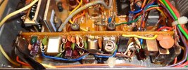
Another revelation, the 2002 is not the PLL. There is an IC under the X-tal I did not see that is a CCI3001. Now to start again getting readings from that IC. Regardless though, I still don't have the 1..24 at the CCI2001
Gets more confusing to me now. Pin1 of the 3001 has 18.205 and pin3 has 10.240. Pin1 of the "sardine can" on the bottom of the circuit board, which would be pin1 on the diagram of the "sardine can" I uploaded is at 10.240.
I think you mentioned this @brandon7861, but it is contrary to the schematic, unless I am really not seeing things correct...which is not improbable.


Last edited:
Contrary to which schematic?I think you mentioned this @brandon7861, but it is contrary to the schematic, unless I am really not seeing things correct...which is not improbable.


If the PLL circuit is anything like the 621 in design, then the first thing coming off pin 9 in the sardine should be a diode (it is for the RX clarifier/tune and prevents the internal varactor voltage from backfeeding everything else on that line that is supposed to turn off during TX). Test that diode. That being open would explain the high voltage present. Does it go low on TX at least? Should be about 8v too, not 9v.
Last edited:
I have to get the channel selector back working and hooked up. The ribbon cable has the insulation peeling, actually more like cracking, off the wires and has no flexibility. I have some ribbon cable on way and it should be here today sometime. Hopefully it will be what I need, or at least allow me to get it put back together.View attachment 66795
If the PLL circuit is anything like the 621 in design, then the first thing coming off pin 9 in the sardine should be a diode (it is for the RX clarifier/tune and prevents the internal varactor voltage from backfeeding everything else on that line that is supposed to turn off during TX). Test that diode. That being open would explain the high voltage present. Does it go low on TX at least? Should be about 8v too, not 9v.
I have the SAMS on the way for this radio, what I have now is a schematic and alignment that a member here posted. Hopefully the complete manual will help me a little more. I am not used to all the extra daughter boards like this 611 has, and it makes it more difficult to find and test where I need to. You probably already know this from my back and forth on my findings. I appreciate you sticking with me on this.
I did trace that pin9, it has a black wire running up to an unnamed diode to R7 and R8, from R8 to vr1 and then to pin1 of the 2002 IC. R7 looks go through a capacitor looks to be coupled to one leg of the X-tal (10.240).
When looking at the board it does show pin9, but if I do a count on the diagram of the SB (sardine board) and count back from the pin 24, and add for the pins that aren't being used on this radio, it would equate to pin17, which shows a reg.+DC out. I don't know, I dabble and try and figure this stuff out as a total novice and try and make some sense of it all. When I get the SAMS hopefully it will open up the clouds for me, and I may be able to more knowingly express what I find for those patient and gracious enough to help me out.
OK, looking around a little more, I find that the Royce 619 shows a Sardine Can PLL that I think is very close to what I'm looking for. They call it an M2 U27 PLL, and that woke me up on what's happening. I'll upload a not very well scanned schematic of it. From this, the pin1 that I have 10.240 out of the SC on my 611 is correct.
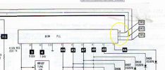
Also, on the schematic I have of the 611, the U-34 is evidently representing the SC as the PLL, not the individual CCI3001 PLL. So this is a mistake I have been making, and it is becoming a little more clear to me.
While looking through the SAMS for the 619 made it a little more clear to me what is happening with the SC. SAMS is taking the SC and representing it as a whole as the U-34 PLL on the schematic. Took me a while to get here, but I think I now have a better understanding of where I need to start looking. I'm always chasing my tail, I wish I had more knowledge on CB repair.
So, after this revelation, at least to me, is that I have the 10.240 at the TP1, and it's still not making it to the pin18 of the CCI2001. Back to the drawing board as they say.
I need an aspirin.
Attachments
I wish I would have seen this before I started messing with this 611. Not the same really, but a good explanation of the Sardine Can. The one in this 1-641 has 2 more X-tals in it than the 611 version, but a good pre-requesite to get an understanding of what Royce does.
He also has what looks to be a "Smith tool" for those radios that don't cooperate.
He also has what looks to be a "Smith tool" for those radios that don't cooperate.
You are correct that Sams represents the entire SC as the "PLL unit". Unfortunately, I do not believe Sams ever went into detail on the sardine cans or their alignment.
Don't count back from pin 24, that SC only has 14 pins. In your picture of the pins, count from right to left 1-8 on the right, 9-14 ending on the left.

Since you have 10.24MHz on pin 1 of the SC but not at pin 18 of the 2001 chip, the next thing I would do is temporarily cut the trace right at pin 18 to see if the signal appears at the trace where you made the cut. If it does, it tells us that the problem is in the 2001 chip. If it does not appear, I would then (before rebridging that cut trace) see if the signal is making it across C119. If it is on one side of C119 and not the other, I would then remove the filter and see if the signal reappears on the other side of C119. If it does come out of C119 after removing the filter, I would suspect a problem with the filter or something after it (which is only a transformer winding to ground). You just gotta eliminate one possibility at a time.
I also saw that 641 video. When I made the schematic for the PLL unit on the 621, I emailed Mike to see if he would swap schematics, 641 SC for my 621 SC. He agreed. So I also have the schematic for the 641 with all his notes if you care to look at either (his notes on it had already made it into the public realm, I had just not found them at the time I asked). However, I can assure you that both schematics are different than that used in your SC. Both the 621 and 641 SC had 24 pins, yours only has 14. I would love to see the schematic for that one if you ever come across it!
Don't count back from pin 24, that SC only has 14 pins. In your picture of the pins, count from right to left 1-8 on the right, 9-14 ending on the left.

Since you have 10.24MHz on pin 1 of the SC but not at pin 18 of the 2001 chip, the next thing I would do is temporarily cut the trace right at pin 18 to see if the signal appears at the trace where you made the cut. If it does, it tells us that the problem is in the 2001 chip. If it does not appear, I would then (before rebridging that cut trace) see if the signal is making it across C119. If it is on one side of C119 and not the other, I would then remove the filter and see if the signal reappears on the other side of C119. If it does come out of C119 after removing the filter, I would suspect a problem with the filter or something after it (which is only a transformer winding to ground). You just gotta eliminate one possibility at a time.
I also saw that 641 video. When I made the schematic for the PLL unit on the 621, I emailed Mike to see if he would swap schematics, 641 SC for my 621 SC. He agreed. So I also have the schematic for the 641 with all his notes if you care to look at either (his notes on it had already made it into the public realm, I had just not found them at the time I asked). However, I can assure you that both schematics are different than that used in your SC. Both the 621 and 641 SC had 24 pins, yours only has 14. I would love to see the schematic for that one if you ever come across it!
I think it is worth mentioning again that pin 9 of the SC (see above picture with pins numbered) should not be at 9v as you have labeled it. It should be around 4v during RX and 0v during TX. After you trace down where the 10.24 is disappearing (in the 2001, in the filter, or a bad capacitor), that would be the next mystery I would solve. I am fairly certain that inside the SC, coming off pin 9, is a diode and that diode (or the resistor to ground after it) is shot.
Edit: center the tune pot and recheck the voltage on pin 9.
Edit: center the tune pot and recheck the voltage on pin 9.
Last edited:
I just wanted to explain why I figure there is a bad diode/resistor in the SC. I have 2 SC schematics, both different with respect to the clarifier/tune control (your pin 9).
The SC Mike reverse engineered did not have the diode I am talking about because the clarifier voltage was divided down to a level appropriate for the varactor elsewhere in the radio. In that SC, there is no direct path to ground, just the varactor and crystal.
In the 621 SC, they had a voltage divider on the vacactor inside the SC that was driven by a transistor inside the SC that is high (8v) during TX. In that SC, the clarifier/tune voltage is closer to the regulator voltage because it also must see the divider that is internal to the SC. Perhaps they did that to lessen the clarifier/tune range by lessening the effect of the incoming control voltage, I don't know. (Edit: Actually I believe it is because they need that oscillator on during TX too, but without clarifier function. The 641 is the same way, but the divider for both TX and RX are external to the SC)
Anyhow, the diode I am talking about prevents the voltage at the internal voltage divider from back feeding into the radio during TX (remember, that line to pin 9 goes low on TX and is also used to turn other things off).
The fact your radio, like the 621, has near-regulator voltage going to the pin (as evident by the schematic and your measurement), it would suggest the SC can tune section is more similar to that of the 621 than the 641. And going off that schematic, the backfeed prevention diode, or the resistor to ground in that internal divider, are the prime suspects for not pulling the voltage on pin 9 down to what the Sams says it should be.
Last edited:
dxChat
- No one is chatting at the moment.
-
-
dxBot:63Sprint has left the room.
-
dxBot:kennyjames 0151 has left the room.
-
-
