• You can now help support WorldwideDX when you shop on Amazon at no additional cost to you! Simply follow this Shop on Amazon link first and a portion of any purchase is sent to WorldwideDX to help with site costs.

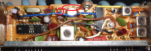
Mixer IC I think

I think it is worth mentioning again that pin 9 of the SC (see above picture with pins numbered) should not be at 9v as you have labeled it. It should be around 4v during RX and 0v during TX. After you trace down where the 10.24 is disappearing (in the 2001, in the filter, or a bad capacitor), that would be the next mystery I would solve. I am fairly certain that inside the SC, coming off pin 9, is a diode and that diode (or the resistor to ground after it) is shot.

Edit: center the tune pot and recheck the voltage on pin 9.
I get it, I will check and see. I seem to lose the 10.24 at C119 a 22pf. I have it on one side closest to the pin1, but lose it on the other side. I pulled the diode and it shows 24pf...should I even be able to see it on the far side? Not sure all this RF stuff and signals work. It's all a learning experience to me. I will pull the diode and test it.
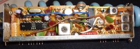
Here's the SC from the 611 pulled.

Which tune pot are you referring to?, VR1 on the SC?
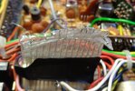
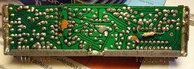
royce_pll_component.JPGPLL_roycefoil.JPG
 
I think I see which diode to test in that picture (the one by the black wire) but I want to try to put those pics in photoshop and overlay them with a little transparency to match the traces to the parts. I have aphantasia (no visual memory/imagery, essentially no "minds eye", can't "picture" things), looking at one side then the other and making sense of it is nearly impossible for me.
 
I think I see which diode to test in that picture (the one by the black wire) but I want to try to put those pics in photoshop and overlay them with a little transparency to match the traces to the parts. I have aphantasia (no visual memory/imagery, essentially no "minds eye", can't "picture" things), looking at one side then the other and making sense of it is nearly impossible for me.
I think the VR you meant is VR107, I see it in the schematic, but not on the board...still looking.
I see the point [4] is supposed to be at 7.9V as well, and that is the 9V I'm seeing. So I think it might need to have that 9V at reference [4] reduced somehow to the 7.9V.
 
Last edited:
and if you want the photoshop psd file to play with the opacity (layer 1)....
pll trace.png
zipped to make file extension allowed
 

Attachments

  • 611 pll unit trace overlay.zip
    8.6 MB · Views: 1
I think the VR you meant is VR107, I see it in the schematic, but not on the board...still looking.
I see the point [4] is supposed to be at 7.9V as well, and that is the 9V I'm seeing. So I think it might need to have that 9V at reference [4] reduced somehow to the 7.9V.
Its the tune pot on the front of the radio
 
Which tune pot are you referring to?, VR1 on the SC?
Oh crap... Shouldn't have turned that. That is not inline with the diode and resistor, it merely shares a common ground with that resistor (via the metal can next to it if you follow the traces). Now we need to figure out what that pot does and set it back to where it was :( Looks like another PLL is about to get reverse engineered.
 
Yep, that drops the voltage, from 1 to 9 volts, and in between.
So it is like the 621 in that the internal divider handles TX and the external divider (the tune pot) controls RX. We can ignore that 9v on pin 9 issue then.
I wonder if the R310 at 470 ohms is failing. That is the 7.6V source, and it's at 9V?
I mentioned the reg voltage being too high earlier... Now that we can ignore the unusually high voltage on pin 9, I will go look at this R310 part of the schematic next. BRB
 
what voltages do you have on the legs of Q401?

There is a good chance zener D403 gave up the ghost and let the supply voltage reach the base, those measurements will tell us.
 

dxChat
Help Users
  • No one is chatting at the moment.