• You can now help support WorldwideDX when you shop on Amazon at no additional cost to you! Simply follow this Shop on Amazon link first and a portion of any purchase is sent to WorldwideDX to help with site costs.

Modified Vector 4000

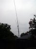
Hey Mack, really is a nice big image you got here, helps us old guys see better. Can you tell me how far from the bottom end of the lower tube #2 did you place the aluminum bracket #1? Or, did this bracket come attached to the bottom tube #2 from the factory? The image I'm talking about can be seen in image #6 of the mounting instructions.

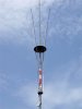
Very good work Henry. If you can get the correct measurements and are willing to do another model of the New Vector 4000 with the basket on top, then we'll have a bases point to start evaluating the Vector. Otherwise we'll be all over the place with different ideas, different styles and construction, and likely with different results.
 
I know the first impulse will be to laugh at the feeble bumbling experiments of the uninitiated efforts of the likes of HomerBB, nevertheless, armed with only the will to try anything within my limits, and the interesting posts you real antenna gurus write, with the modest little SWR meter I own, I venture into the sacred providence of the mighty.

So, I took my 5/8 wave, extended it to 27' 11", removed the coil and built a gamma for it, reversed the drooping GP aerials to an upside down position, made a wire ring od 30" diameter for the aerials, and used an end of a rope spool for spacer on the aerials.


Can't work on it anymore today - it is raining now and I must work today.

So far, at 10' to feed point,

SWR
27.405 --------- 1.5:1
27.195 --------- 1.4:1
26.965 --------- 1.3:1

Got only one photo as the rain started. The vertical is longer than the photo shows. I didn't get a better shot due to the rain coming suddenly.
Before
no06a.jpg


After
 

Attachments

  • 3719.jpg
    3719.jpg
    98.2 KB · Views: 167
  • 3720.jpg
    3720.jpg
    132.3 KB · Views: 170
  • 2721.jpg
    2721.jpg
    76.2 KB · Views: 167
Last edited:
Looks outstanding Homer, keep us posted on how it performs compared to the 5/8 wave.

You're quite the Rube Goldberg.
 
Took a few minutes to spin around the dial on the radio at ten feet elevation.

27.395 LSB -------- 977 Bob, Tuscaloosa, AL
27.375 LSB -------- 244 Indiana
27.275 AM -------- 252 Kentucky

Also two or three other on LSB on 27.505, 485, 425

I'll get it up where the 5/8 flew first chance - maybe tomorrow - and we'll see.

Homer will you be making any local signal comparisons between the 5/8 wave and the new antenna when you get it raised up a bit?

I'm curious how you came up with the length you used and did you have to change that as part of your tune?
 
Last edited:
I got the length from the discussion itself, with the lengths stated to be from 27.5 to 29.5, and sometimes as 31.5 feet. It was the length of aluminum pipe I had on hand so I couldn't go longer. :blink:

Yes. I could not get a good SWR without adding the length. It wouldn't tune with 5/8 wave length. I tried two different gamma matchers before adding length. The resulting SWR is where it landed with the new length. I will be trying for better soon as I can.
And yes, I will be trying to do some local comparisons, however, the volume of skip lately runs off most of the near-distant local stations as they don't favor the commotion.

I have it up on the house, now.
I wanted it where the dipole is, and a little higher, but the wind is too strong for me to handle it on my own today.

As it is i can tell a lot of difference between it and the dipole, but comparisons locally with the past performance of the 5/8 will wait until I can ratchet jaw with some stations in the area.
 

Attachments

  • 3724.jpg
    3724.jpg
    82.1 KB · Views: 154
  • 3728.jpg
    3728.jpg
    101.6 KB · Views: 155
  • 3723.jpg
    3723.jpg
    148.5 KB · Views: 152
Last edited:
  • Like
Reactions: Shadetree Mechanic
I have to ask some of you if you think making the four aerials of bigger material would affect/improve the antennas potential performance?

The center vertical ranges from bottom to top with 1.25" to .5" all aluminum.

The four aerials are of wire supported by fiberglass poles. I am thinking of making the entire 3/8" fiberglass poles metal. Perhaps a heavier (more surface area) ring on top, too . . . it is #12 steel wire, but quite stiff/sturdy.

I would note that the addition of the circle to the radials brought the SWR under 1.5:1 without touching the gamma from over 6.1:1 SWR.
I haven't real clue what I'm doing here, but it is still fun.
 
  • Like
Reactions: Shadetree Mechanic
Hi All,

I am searching for "exact" measures of the antenne.
I can find the sizes of the antenna back in "82... but i would like a more "modern" version.

From the Sirio homepage i have so far:
Radials bottum 13mm thick 1,4 meter long going over in 10mm thick 1,31 meter
So the total radial length would be 2,71 meter.

The Radiator length total is 8.48 meters.
The diameter starts at 37mm and is 1,4 meters long.
second tube is a 33mm 1,4 meter long

Everything else is a guess to me.

With guessing....
third tube 29 mm 1,4 meter long
fourth tube 25mm 1,4 meter long
fitfth tube 21mm 1,4 meter long
sixth tube 17 mm 1,4 meter long
seven tube 13mm 1,4 meter long.

Could someone give me better sizes?

(inches feet also fine!)

The biggest question for me now is :the top distance of the radials to radiator.(where the round circle is).

Kind regards,

Henry

Henry,

The distance between the top of the radials and the outside edge of the main radiator is 14.5 inches or 36.83 cm. This is the same distance on all models from the Sigma IV to the new Vector.
 
Henry, Mackmobile says the bottom hub comes installed on the lower 55" section of the radiator and is is 14.5" from the middle of the hub to the bottom.

I also notice that the top element measurement L3 does not include the wire basket on top, so I guess the length of the basket is not included in the 8480 mm overall length either, but I'm not sure.

I have not been able to find out the lengths for each of the 5 section whip, but Mack says they arrived all inside each other and they were all the same length. He also thinks the overlap was 3" - 4", but not sure.

The two bottom sections are 55' each and I do not know the overlap there either, but I figure maybe it could be 5" and make the top section #10, equal 50" installed. I also -minus the base mounting section of 14.5" from the base section #2 an it leaves about 40" - 40.5" exposed for the bottom section.

I figure all measurements from the middle of the bottom hub, so from there to the top end of tube #10 is approximately 90.5". This point is where the 5 section whip starts and for this section to work out to the overall length of 334.11" each of the 5 sections needs to be 40" to equal 334".

If the hoop is the same on all these antennas, then I figure the circumference is 94.5" / 30" = 3.15 which is
pi.gif
and agrees with the formula and Bob is correct.

I think the radials are given as a overall total of 2710 mm = 106.8".

Here are my estimates:
Vector 4000 dimensions.jpg
 
I also notice there is a flaw in EZNEC+ that reports an exaggerated reduction in gain as the main radiators diameter is increased. With the radiator diameter at just over 1 inch tubing, the programs reports close to unity gain. This is obliviously not correct. At the same time no changes in the radiation plot can be seen. I wish I knew why the program reports such a huge change in gain with diameter but the in field tests show the gain closer to 5.15 dbi with 1 inch diameter main radiator.

The program reports a gain within 0.1 db of actual field strength tests compared to a dipole when modeled as a wire conductor rather then tubing. While there may be flaws modeling the Sigma in EZNEC the program is still producing the most accurate models I've seen in 30 years for the antenna and helped me to understand more about how it works. I gave Bob85 some of the results I got with the program modeling the new Vectors dimensions. Perhaps he will post some of the screen shots since I'm having problems uploading images.
 
here you go, intersting plot,
i agree tube diameter ratios effect the antenna but i don't believe that gain falls like a stone.

thanks (y)

wires2.png


antcurrent-1.jpg


antpattern.jpg
 
lol, currents looks similar to my EZ-BOB plot,
i made radial current magnitude exagerated/equal to monopole current for ease of viewing, kirchoff tells us the current will be shared between the radials giving the lower current magnitudes seen in your EZ-NEC+ plot:laugh:,
 
I would like to point out that we would not have any of these computer modeled statistics if it were not for the efforts Henry HPSD put into building the basic model of the Sigma IV in EZNEC. I also noticed the radiation currents looked very similar to the drawings Bob85 made.
 

dxChat
Help Users
  • No one is chatting at the moment.