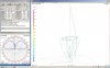
DB, if you will show us your Vector model in free space. I think you are reporting what you see in your model over real Earth and nosepc might be talking about an angle using a free space model. That should show us the higher maximum RF angle nosepc is reporting he sees. My free space model of my Vector doesn't show as much angle as he is suggesting, and your model may not either, but I see this higher maximum angle, using Eznec FS feature for all of my antennas that are NOT well balanced...as with center fed antennas.
I was using real, nosepc was using perfect earth. Our antennas are also at different heights, different radial angles, and his has a loop while mine simply has upward pointing radials. That being said I'm happy to show you my vector model in free space...
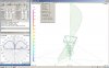
DB, can you also describe to me what steps you take to make a FS model in 4nec2? Example: if your model has a mast...do you have to remove it in order to get a good FS pattern? With Eznec, I also have to remove any material resistance losses I used too.
As the model didn't have a mast in this case to begin with I simply changed the ground from real to freespace... I know I should factor said mast/coax into the model, however, this time I didn't. I was trying to get specific results in what is akin to a lab environment before I attempted to simulate part of the real world as well...
Can you also tell me if 4nec2 also reports model accuracy with its free space models like Eznec's Average Gain test does?
If not, how do you know that the feed point is located correctly for an antenna that is going to show you a mismatch without a matching device?
Model accuracy??? Not come across anything with that specific name. Perhaps it is called something else in 4nec2?
As far as the feedpoint is concerned I'm putting mine at the base of the 3/4 wavelength vertical, although it should be higher, and have a capacitive load to simulate the gamma match. Perhaps a split feed as you mentioned in another thread (I think it was you). I have yet to try and match an unmatched antenna with modeling, and am unfamiliar with its effects onthe models themselves aside from some basic information.
In the model you posted earlier, where you changed the wire connections and got phase differences in your output, could you describe those connections by wire and end number for the radials that you changed vs the way 4nec2 made the connections originally using its default radial creation feature?
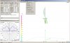
I actually made the radials by hand in all of my vector models. Some simple math and I can get very close to pretty much any angle I want and any length I want. That being said, I have played with 4nc2's cylinder tool, that is the tool that will create an angled set of radials for 4nec2, and have been able to create this type of angles radial setup with coordinates "both directions".
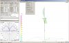
The way I manually made the radials to show the radials as being in phase with the upper 1/2 wavelength of the vertical 3/4 wavelength element is as is shown below... Namely the XYZ1 is at the base of the 3/4 wavelength vertical element and XYZ2 are the tips of the various radials.
Type Tag Segs X1 Y1 Z1 X2 Y2 Z2 Radius
Wire 1 24 0 0 5.5 0 0 13.75 .0001
Wire 3 8 0 0 5.5 .87 0 8.109 .0001
Wire 4 8 0 0 5.5 -.87 0 8.109 .0001
Wire 5 8 0 0 5.5 0 .87 8.109 .0001
Wire 6 8 0 0 5.5 0 -.87 8.109 .0001
XYZ are in meters, Radius is in millimeters. I used such a tiny radius because 4nec2 seemed to have trouble with the angles used even at 1/10 of a millimeter...
When you made the changes in connections did you do that manually or does 4nec2 provided tools that will handle such changes?
Manually.
Just a note, math has always come easy for me, so it really isn't difficult for me to calculate points and line lengths on a three dimensional grid. I like to do as much of this manually as I can, it helps me stay sharp with these types of equations, and if I make a mistake I can troubleshoot my own process and correct it rather than depending on someone else's tool. I have played with the different geometry tools that came with 4nec2, however, unless I'm looking for something that is to complex to make myself I doubt I'll use them.
The DB