• You can now help support WorldwideDX when you shop on Amazon at no additional cost to you! Simply follow this Shop on Amazon link first and a portion of any purchase is sent to WorldwideDX to help with site costs.

Solarcon A99 Experimental Results and Analysis of Ground Plane Radials

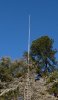
I suppose I live in fantasy-land then considering that I witnessed a very tangible and statistically significant increase in the distance covered under a full-bar full-quieting signal. The magic elves must be up to their antenna magic again ;-)

No, you merely don't understand antenna theory.

If you're using a horizontal dipole and the other station you're communicating with via ground wave is using a vertical antenna you'll see an automatic 20dB loss due to being different polarities than you would if you were both using the same polarity. So if you then switched to a vertical, if you don't know about antenna theory you'd come to the conclusion that the vertical worked better and had more gain when that is not the case.

My knowledge of antenna theory is just fine. Your knowledge of the topic at-hand is clearly challenged. What do cross-polarization losses have to do with anything remotely relevant to this discussion? I'm talking about the effects of adding radials to the Solarcon A99. The base antenna is clearly vertical. The mobile antenna I used on the receive end was also vertically polarized. I drove the same route N/W/S/E comparing the distance covered by a full-quieting FM signal in which the signal strength indicators were maxed out on the receiver. The addition of the four 1/4 wavelength radials to the A99 increased the range covered per those parameters by approximately 20-25%. That to me is a statistically significant and tangible "real-world" improvement to the general performance of an A99 without a ground plane installed. So for local talk, the radials are clearly beneficial. It is far more difficult to assess whether the radials were beneficial or detrimental to DX performance.
 
The difference between an end fed 1/2 wave and a 1/2 wave with radials is insignificant. The difference you are seeing is a matter of feed line isolation (by means of those radials) rather any 'groundplane' issues/abilities. The same thing could be done by means of a choke of whatever type. The radiation pattern (the significant thingy) of that 1/2 wave isn't changed at all. It isn't a simple 'yes/no' kind'a deal.
- 'Doc

(Don't like or understand that? Sorry 'bout that.)

I don't particularly like it, but no need to be sorry ;).

I don't like that explanation because it simply doesn't adequately describe the situation. The fact is, feed-line isolation should have already been addressed. Prior to even going down the "radial road", I already had an 8-turn coax choke at the feed-point with a pair of snap-on ferrite chokes on either side of the coax choke to further suppress common-mode currents. So how does your logic coincide with this fact? If I already had feed-line isolation accounted for, with the "means of a choke of whatever type" as you describe, then the radials should not have produced the tangible improvements that they did.


I think it is somewhat naive to just say "case closed, don't believe your eyes, nothing to see here folks" as it pertains to the addition of radials to an end-fed half-wave like the A99. In theory, a half-wave dipole should only have 2.15 dBi of gain -- period. But we do not operate our antennas in the vacuum of space. We operate them on earth where more complex interactions occur with the environment. I've seen plenty of models and write ups demonstrating that 1/2 wave antennas can and do present more than the predicted gain of 2.15 dBi because of their unique interactions with ground. I find it interesting that so many people are so dismissive and quick to judge on this topic without doing any hands-on investigation into the matter. So I shall gladly continue to beat this dead horse that is the A99 and a ground plane...:bdh:
 
So for local talk, the radials are clearly beneficial. It is far more difficult to assess whether the radials were beneficial or detrimental to DX performance.

The only way you could've got that kind of increase is if the antennas were differently polarised. No amount of adding radials would increase it by that. None.

Increasing the height 20-30ft or more possibly could but not adding radials.
 
I already had an 8-turn coax choke at the feed-point with a pair of snap-on ferrite chokes on either side of the coax choke to further suppress common-mode currents.

Meaningless unless you know the mix of the ferrites and you checked the choking impedance of the coil with a grid dip meter.

I've not seen 8 turns mentioned anywhere for a coax choke for 10-11m. If you look at G3TXQ's chart of RF chokes where the air cored ones are at the bottom, you'll see a difference of adding just two turns on a 4.25" core can change the choking from more than 8k Ohms on 27-28MHz to just 500 Ohms, moving the frequency where it chokes at 8k Ohms down 6MHz.

So if you are using snap on ferrites with no idea what mix they are and a random air cored choke you could have either a lot or bugger all choking and given that it is reactive you could be increasing common mode current.

I've seen plenty of models and write ups demonstrating that 1/2 wave antennas can and do present more than the predicted gain of 2.15 dBi because of their unique interactions with ground.

Solarcon claim 9.9dBi for the A99. I've modelled half wave antennas over real ground and perfect ground at all kinds of heights and never seen that.

How are you coming to the conclusion about the gain? What are you using other than anecdotal evidence?
 
Absolutely your privileged, keep beating away.
A couple of things to keep in mind. A coaxial choke with or without ferrite on either end, are frequency specific in size (reactance). Depending on the reactance produced by your particular choice it may not be enough or too much, it works both ways.
As for that 2.15 dBi for an isotropic 1/2 wave dipole, that's a 'numbers' anomaly dealing with 'isotropic space'. It's not just for 1/2 wave antennas, it's for all isotropic antennas, 1/4 wave groundplanes for instance. Subtract 2.15 dBi to convert to 'real life' gain figures (dBd). All of the NEC modeling programs are only approximations because all information/data required for accurate prediction is almost impossible to furnish the program, at least for the average user. And then it's for only one particular set of circumstances.
Have fun...
- 'Doc
 
Yes. Got one given when I bought a used A99. Made no noticeable difference other than the antenna swaying about more in the wind. Gave it away to a passer by who expressed interest.

I'm guessing that kaosfm should put an analyzer on his antenna just to see what it's doing. As for me,I'm going to run my A99 and eventually get an analyzer myself to tune it correctly. So far I'm happy with my A99's performance although I'm pretty sure it can be tuned better than what I have it.
 

Attachments

  • image.jpg
    image.jpg
    925.9 KB · Views: 20
Last edited:
I'm guessing that kaosfm soukd put an analyzer in his antenna just to see what it's doing. As for me,I'm going to run my A99 and eventually get an analyzer myself to tune it correctly. So far I'm happy with my A99's performance although I'm pretty sure it can be tuned better than what I have it.

Hi Lil'Yeshua,

I would love to put an MRJ-259 on there and see what is going on. If only I owned one! I am such an OCD-freak though when it comes to constantly tweaking the antenna, the feedline, the mast, the radio, the amp, etc. that an MRJ-259 would be a dangerous investment lol.

BTW...those 102 inch whip radials on your A99 look like they would be quite a strain on the support hub. Are there any signs of fatigue that are obvious or does it hold up quite well under those conditions? It would be interesting to find out too how much of a difference it would make between using 18 AWG stranded copper wire vs. solid stainless steel for the radials. Perhaps it is inconsequential.
 
Meaningless unless you know the mix of the ferrites and you checked the choking impedance of the coil with a grid dip meter.

I've not seen 8 turns mentioned anywhere for a coax choke for 10-11m. If you look at G3TXQ's chart of RF chokes where the air cored ones are at the bottom, you'll see a difference of adding just two turns on a 4.25" core can change the choking from more than 8k Ohms on 27-28MHz to just 500 Ohms, moving the frequency where it chokes at 8k Ohms down 6MHz.

So if you are using snap on ferrites with no idea what mix they are and a random air cored choke you could have either a lot or bugger all choking and given that it is reactive you could be increasing common mode current.


Solarcon claim 9.9dBi for the A99. I've modelled half wave antennas over real ground and perfect ground at all kinds of heights and never seen that.

How are you coming to the conclusion about the gain? What are you using other than anecdotal evidence?


Great feedback, thank you! I based my 8-turn 8" diameter choke on the "8-8" rule described here: RF Choke Coil - K3DAV - Amateur Radio Operator

However, choke dimensions for 11-meter seem to be one of the most disputed topics out there (much like the A99 and a ground plane). I read so many variations that I wasn't sure what the authoritative answer was and eventually settled on the 8-8 rule because it appeared to be a compromise between many of the dimensions called out. I always like to base my actions on empirical evidence whenever possible and g3txq's chart appears to have greater validity in that regard. I think I will modify the choke accordingly and repeat the experiment. Perhaps it will reveal a different conclusion.

BTW...what is your take on choke location/placement? I have seen "immediately at the feedpoint", "12-24" below the feedpoint" and finally "1/4 wavelength below the feedpoint". I settled on option 2 because it was a compromise. That may very well be a mistake.

In terms of the 9.9 dBi gain claim, I certainly don't believe that value...it is absurd. I am basing my assertions on the modeling by w8ji below. I don't necessarily buy into the 8.5 dBi figure either, but I believe there is a distinct possibility that half-wave antennas in the HF spectrum can exhibit gain figures beyond the theoretical 2.15 dBi.

"A dipole does NOT have 2.2dB gain over an isotropic radiator when the dipole is placed over earth. At optimum heights, a common 1/2 wave dipole actually has about 8.5 dB gain over an isotropic radiator! Always remember that when you see antenna models over earth that tell you an antenna's gain in dBi.

If a model over earth shows a "gain" of about 8.5 dBi, the model effectively has the same gain as a dipole at optimum height over typical earth! We cannot add 2.15 dB to the isotropic gain to get the dBi gain unless ALL of the antennas are in free-space! The instant the earth is involved in a model or measurement the 2.15 dB rule flies out the window."​
 
Awesome! That looks quite sturdy to me. Is that from the actual GPK-1 ground plane kit or is that from another manufacturer?

It's the GPK-1 ground plane kit. I had four 102" SS whips so I used those. Some of the guys in this forum said they'd work better than the six foot fiberglass radials that come with the GPK-1. Plus Marconi did some antenna modeling for my configuration. Here's the modeling Marconi did for me.
 

Attachments

  • image.jpg
    image.jpg
    70.1 KB · Views: 79
  • Like
Reactions: CB590

dxChat
Help Users
  • No one is chatting at the moment.