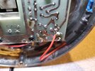
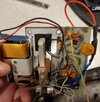
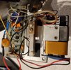
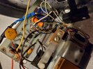
The adapter you put the link for is the correct one. It's wired the same as the 94hpc so as long as your 4 pin mic is wired cobra galaxy it should work.After messaging with the Ebay vendor, the 4 pin to RJ45 adapter I got is not compatible with the Astatic D104 or D104-M6B and Anytone RJ45 plug.
I am returning this adapter and will be getting a different one.
But since the wires for pins 1 and 3 are actually touching, I don't think this D104 will work with any radio at the moment, including the Anytone.
So until I get the replacement adapter, the stock mic has been reconnected and I am enjoying the Q5N2 again. It really is a nice rig!
You are using an out of date browser. It may not display this or other websites correctly.
You should upgrade or use an alternative browser.
You should upgrade or use an alternative browser.
-
You can now help support WorldwideDX when you shop on Amazon at no additional cost to you! Simply follow this Shop on Amazon link first and a portion of any purchase is sent to WorldwideDX to help with site costs.
-
A Winner has been selected for the 2025 Radioddity Cyber Monday giveaway! Click Here to see who won!
Anytone at-5555n II (version 2)
- Thread starter Eldorado828
- Start date
@ Eldorado & TimmyThe rj45 only uses 3 pins, rx is not used. Voltage for the stock electret is provided through the audio pin so you SHOULD NOT use any power mic with the radio in el mode.View attachment 62063
@ Eldorado
Thanks for the RJ45 wiring info. You confirmed my suspicion about the channels being on TX. Which means there is voltage on TX as well - partial grounding of that voltage is how the channels work.
No offence meant, but I disagree with your last comment.
Why does a Power mic make any difference? The E/R switch has nothing to do with the audio line. It switches between PTT Electronic and Relay switching for the D-104. You said there is no RX, so Relay switching is impossible (RX & TX are connected together). In the Relay position, the radio won't key, it will just change the channel - Which is exactly the problem Timmy is having.
A Cobra 4 pin mic uses Electronic switching. TX and RX are connected to shield/ground, not each other.

The D-104 has the ability to use Electronic or Relay switching. For models that have a E/R switch, the Blue wire is the "common" on the PTT switch. This is so it can be used with a 5 pin Cobra, etc. which doesn't use shield to switch PTT (it uses a separate ground) or an older radio that uses Relay switching.
For the D-104 to be properly wired for a Cobra 4 pin, the switch must be in the "E" position and the mic plug should be wired (assuming stock colors):
Pin 1 - Bare copper shield and Blue wire (Ground & PTT common)
Pin 2 - White wire (audio)
Pin 3 - Red wire (PTT TX)
Pin 4 - Black wire (PTT RX)
N/C - Yellow wire
The Female 4 pin mic plug on the RJ45 adapter should be wired:
Pin 1 - Black (shield)
Pin 2 - White (audio)
Pin 3 - Red (TX/UP/DW)
Pin 4 - N/C
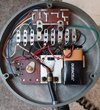
@TimmyTheTorch - Would you mind popping the base plate off your D-104 and take a picture so we can see what the "New Internals" are. I don't want to lead you down the wrong path if something is not stock. And I don't think it is because your picture of the mic plug shows a Blue wire and shield together. The TUG8 stand with the e/r switch only had 3 wires and a shield (no Blue wire). So something isn't "stock" with your D-104.
Thanks,
Dr_DX
@ TimmyTheTorch
"But since the wires for pins 1 and 3 are actually touching, I don't think this D104 will work with any radio at the moment, including the Anytone."
Yes that is a problem....
Another problem is that your D-104 mic plug is not wired correctly for a Cobra.
The White wire currently on Pin 1, needs to be switched to pin 2 and the Blue/shield on pin 2 needs to be switched to pin 1
Good Luck.
Last edited:
Dr_DX is just overflowing with good news today. Geesh.@ TimmyTheTorch
"But since the wires for pins 1 and 3 are actually touching, I don't think this D104 will work with any radio at the moment, including the Anytone."
Yes that is a problem....
Another problem is that your D-104 mic plug is not wired correctly for a Cobra.
The White wire currently on Pin 1, needs to be switched to pin 2 and the Blue/shield on pin 2 needs to be switched to pin 1
Good Luck.
At least the mic looks pretty.
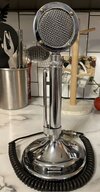
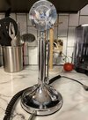
Last edited:
Just for comparison purposes.
View attachment 62076
What should I make of the differences between the one I posted and the one here. The are obviously very different. Is your photo of one with the pre-amp? Or is mine basically made out of bits of discarded garage door openers?
I'm actually not very familiar with this microphone, other than owning one. From what I can tell initially is the switch. E/R, which is what I believe is electric, or amplified and dynamic. There seems to be a lot more going on as well. ??
Just thought I'd put it out there and see if the pot gets stirred.
Just thought I'd put it out there and see if the pot gets stirred.
Since I am now into areas pertaining more to the D104 itself than the Q5N2, maybe I should discontinue this line of discovery in this thread and move it to a more suitable home. I don't want to pollute this Q5N2 thread too much.
On a mic E/R is usually Electronic or Relay keying, which you would set to match your radio. I have not run across one that would allow you to bypass the amplifier in the mic. Not saying they don't exist, I just haven't seen one.I'm actually not very familiar with this microphone, other than owning one. From what I can tell initially is the switch. E/R, which is what I believe is electric, or amplified and dynamic. There seems to be a lot more going on as well. ??
Just thought I'd put it out there and see if the pot gets stirred.
@Brother DXer
You have an older amplified TUG8 stand that appears to be totally stock. 3 conductors and a shield:
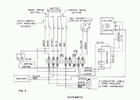
Chicken choker on the side, no push bar on the bottom. 2 switches (E,D,F - grounds out audio when unkeyed and connects the battery negative to ground when keyed) and (B,A,C - controls PTT connected to the E/R switch) that are located in the neck of the mic stand.
The E/R switch has to do with how the radio is keyed. It has nothing to do with mic audio or the amplifier or mic element type, etc.
Older Ham and CB radios use "relay" switching to key up. This means that the RX (switch connection B&A) and TX (switch connection C) wires have to connect to key the radio - there is no ground involved nor is it needed.
Later model and current radios use "electronic" switching to key up. This involves connecting the RX (switch connection B) and TX (switch connection C) wires to ground (switch connection A). The RX and TX wires never connect together.
Your mic is set for Electronic switching.
Great information @Dr_DX . I greatly appreciate you sharing the knowledge!!@Brother DXer
You have an older amplified TUG8 stand that appears to be totally stock. 3 conductors and a shield:
View attachment 62078
Chicken choker on the side, no push bar on the bottom. 2 switches (E,D,F - grounds out audio when unkeyed and connects the battery negative to ground when keyed) and (B,A,C - controls PTT connected to the E/R switch) that are located in the neck of the mic stand.
The E/R switch has to do with how the radio is keyed. It has nothing to do with mic audio or the amplifier or mic element type, etc.
Older Ham and CB radios use "relay" switching to key up. This means that the RX (switch connection B&A) and TX (switch connection C) wires have to connect to key the radio - there is no ground involved nor is it needed.
Later model and current radios use "electronic" switching to key up. This involves connecting the RX (switch connection B) and TX (switch connection C) wires to ground (switch connection A). The RX and TX wires never connect together.
Your mic is set for Electronic switching.
73
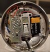
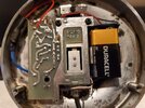
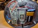
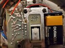
Well the felt on the bottom smells like a mix of cigarette smoke and monkey ass. Going to have to do something about that if this mic doesn't turn out to be a total dud. I don't see a switch anywhere on/in it. Nor do I see much in the way of anything that looks newish/rebuiltish.
View attachment 62066View attachment 62067View attachment 62068View attachment 62069View attachment 62070View attachment 62071View attachment 62072View attachment 62073
@TimmyTheTorch
Your Silver Eagle has the T-UP9 version mic stand (latest). 5 conductors and a shield.
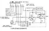 By the time this version came out, there wasn't any current production radios that used Relay switching, so no need for a E/R switch. Having said that, all you have to do is connect the Blue and Black wires together (at the mic plug) and you have Relay switching. Conversely, to have Electronic switching, you connect the Blue and Shield wires together (at the mic plug). For switching that uses a separate ground for PTT (usually 5 pin or more), the Blue wire has it's own pin on the mic plug.
Chicken choker on the side, push bar in the base, 3 switches (J,H,G - Controls PTT; F,E,D - unkeyed - connects ground to yellow wire, keyed - connects battery negative to ground; C,B,A - unkeyed - grounds audio, keyed - connects audio to amp) that are located in the base.
Everything looks pretty much stock on your Silver Eagle except 2 things:
There are some added components (under the Black & Blue shrink tube)
And it appears that something is burning a hole through your Amplifier circuit board. Below the screw hole opposite of the battery, you can see on the solder side where it is discolored and starting to turn black in the center - that is caused by a lot of heat. On the component side of the circuit board in that location is a bare jumper wire going to ground and a small disc capacitor marked 470 that is laying on top of it with a Black wire on top of the capacitor. Move the Black wire and lift up the disc capacitor so it is standing straight up perpendicular to the board. Look at the under side of the disc that was touching the bare jumper wire and see if it is black and/or charred. If it is, then the cap was shorting out the side to the ground jumper and will need to be replaced. If the underside of the disc looks Ok, see if you can tell what is getting hot at that area.
As for the mic working with the Q5N II, if you switch pins 1&2 on the D-104 mic plug and make sure pin 3 isn't shorting out to pin 1, it will probably work with the RJ45 adapter you bought.
Good Luck!
The AT-5555N2 uses the same input pin for PTT and the CH UP and CH DN feature.
Connecting the PTT pin directly to "real ground" (0 ohms) will cause the radio to PTT.
The complication is that the radio will do CH UP and CH DN when it detects different resistances across this PTT pin (I can't remember what they are - but around a couple of hundred ohms at most IIRC - but I can measure this later if you like)
This can create a problem where if your external microphone (aftermarket desk mic, power mic, etc,) does not provide a solid "real ground" DC short circuit across the PTT and Ground pins, the radio will not PTT, and will probably see this small resistance (i.e, anything above 0 ohms) as a CH UP or CH DN signal.
FYI - PC to Rig interfaces (like a signalink) or microphones that use electronic / transistor / "soft" PTT switching to "almost ground" might not work well with the AT-5555N2. It really wants to see a relay, or physical switch across that PTT to Ground line, providing a "real ground" close to 0 ohm connection to PTT properly.
Last edited:
So I received my package yesterday. A new 5555N2. Been familiarizing myself with it, somewhat. I've found a lot of things I really like, and a few things that I don't like, but it could be a matter of me just not understanding something correctly.
Instead of trying to address everything at once, I'll just go over these few annoyances one at a time. None of them are major, but still significant.
Can someone tell me if there is a "built-in" preamp that is on all the time? The noise floor at my station, at least when I was testing last night, is non-existent. My Icom 7610 was seeing zero S-units of noise floor on 10 meters at the time of testing.
It was right at the bottom of the 7610 (excellent) meter, with an occasional little "tickling" of the first tiny dot on the meter, which is about a quarter S-unit. This is how it is when there is no atmospheric noise being registered on my 7610. Late at night, it's usually the norm.
Enter the 5555. That thing is seeing a 4-5 S-unit noise floor continuously. If I flip on my 1st preamp on my 7610, it was giving me right at 3 S-units, so with the 5555N II, it was just like having a preamp turned on.
I don't like having a 4-5 S-unit signal when there is absolutely nothing (including atmospheric noise) on the band. I noticed when I was watching the guy who runs "Scott's Radios" (on YouTube) during a QSO he recorded, he's got the same level of noise floor, when there is none. That's why he uses the DNR on 5 ALL the time.
This gets rid of he noise, but degrades the audio quality a bit. And if you look at the meter, it's still there. The DNR quiets it, so that it seems to be gone. But in reality, weak signals are not able to be heard, when on my 7610, they are plain as day, because there is no 5 pounds of hash covering it up.
Yes, I realize that the 7610 is leaps and bounds better than this veritable "toy" (by comparison), but why then do other 10 meter radios show nothing but quiet on this antenna, unless there really IS a legitimate atmospheric noise floor? One that shows up on ALL my radios, including the 7610?
I have put Rangers and HR2510's and Cobra 148's (etc...) on this antenna and they don't show anything on the meter when it's quiet, just like it is right now. While this thing has what seems to be a permanent baseline of 4-5 S-units of hash. This is why Scott keeps his DNR maxed out all the time, because he has that pervasive noise floor that shouldn't be, too. Unless he just has locally generated noise where he's at.
This radio is supposed to have a good receiver. Yes? That's one of the very main reasons I bought it.
So back to my question... Does anyone know if this radio is preamped full time, and is there any way to shut that off? The RF Gain needs to be scaled back a lot to get rid of that signal on the meter, and doing so also makes the radio deaf to signals that would otherwise be easily copyable.
I'm by no means a "perfectionist" I don't expect an "always noise-free" band, but after 50 years of radio experience in CB, Amateur, and commercial radio, I know when something is not right. I know when the band is totally quiet, and when there is an ACTUAL noise floor. And not one that ONLY one radio "sees".
So my question boils down to this...
Is there a way (other than reducing the RF gain), to switch off any built-in preamp that seems to be on? Or will I always be looking at a minimum of a 4-5 S-unit noise floor, when there should be none?
I have a very quiet location, so it makes me wonder what it will be like during the day, when there's often more atmospheric hash under the skip. Am I going to see a 6 or 7 noise floor? More? lol... On 10 meters?
If this radio has a preamp, that would explain everything, since it matches the signal my 7610 sees, with it's preamp on.
Any thoughts or suggestions? I don't really look forward to a permanent (always present) noise floor that isn't even really there.
D
Last edited:
dxChat
- No one is chatting at the moment.
-
dxBot:brandon7861 has left the room.
-
-
-
-
@ boniface95:Hi there, I just posted this question, if anyone has time to check it out, i'd really appreciate some feedback. https://www.worldwidedx.com/threads...-radio-transmitters-in-the-same-space.270736/

