You are using an out of date browser. It may not display this or other websites correctly.
You should upgrade or use an alternative browser.
You should upgrade or use an alternative browser.
-
You can now help support WorldwideDX when you shop on Amazon at no additional cost to you! Simply follow this Shop on Amazon link first and a portion of any purchase is sent to WorldwideDX to help with site costs.
Utica, Town and country 111 cb radio. shorting out.
- Thread starter klj2497
- Start date
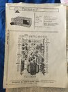
Been stuck at home, used the diagram sample you posted, since all my Sams books are at work. Kinda depends on how the control is hooked up. If you posted the part of the schemo showing the receiver and RF Gain control I would venture an opinion. But if you look at the Sams diagram, you'll see an arrow alongside the symbol for a front-panel potentiometer control. The arrow points to the clockwise end. A 10k fixed resistor wired to the two outside terminals takes care of that. The wire for the center lug just gets moved to the end of the control where the arrow on the diagram is pointing.
73
73
Um, don't suppose you tried to read the PDF above?
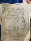
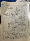
Just too little resolution to identify most components.
73
Just too little resolution to identify most components.
73
I tested around and I realigned A15 A14, A13 A12. some of the lugs don't work, A15, and the top lug 14 of 14/13. also, v1 pin6 should be 75vdc. its 152vdc. The 5pin should be 115vdc, its 153vdc. I know we can fix this dang thing my friend. It's gonna sound great with my sure 444D i can see the meter swing. It dead keys about 7-8 watts And it really pegs the modulation meter on the radio Thanks lol
Shoulda pointed out the ultimate test for the RF Gain control. Just short across it with a screwdriver tip or gator-lead jumper wire. At the full-clockwise position, the RF Gain control is at zero ohms. The reading on V1 pin 2 suggests you are not getting a current path to ground through the RF Gain control, or there's a physical break in the circuit between V1 and the control itself.
73
73
Does suggest that one of the two crystal oscillators needed to receive is not running. Do you have a ham or shortwave receiver that can tune in M24 at 9.979 MHz? Or the selected crystal on the channel selector between 8.36 and 8.5 MHz?
If either of these oscillators is shut down, that's what's blocking the tracks.
73
If either of these oscillators is shut down, that's what's blocking the tracks.
73
Okay thanks Nomad. i will check that. my friend when i was hooking up the signal generator on the bottom side to try another alignment the negative touched something pop. and went off . now it has no ground to chassis. i cannot read anything using chassis for ground. i tested 2 red wires connected to red/yel. they are 38ohm correct. so far okay more to check though
dxChat
- No one is chatting at the moment.


