
You are using an out of date browser. It may not display this or other websites correctly.
You should upgrade or use an alternative browser.
You should upgrade or use an alternative browser.
-
You can now help support WorldwideDX when you shop on Amazon at no additional cost to you! Simply follow this Shop on Amazon link first and a portion of any purchase is sent to WorldwideDX to help with site costs.
Cobra 148 gtl china model
- Thread starter kaos513
- Start date

here is the schematic for your radio. you can use it to trace where each leg goes.
http://downloads.cobra.com/CB/Models/148-SERIES/148_GTL_Late_Model/148GTLschematic.pdf
http://downloads.cobra.com/CB/Models/148-SERIES/148_GTL_Late_Model/148GTLschematic.pdf
Was beginning to wonder what a LM7809 was doing in that radio. There should be a TIP replacement for your original part as a replacement. Might want to look it up.
Is the schematic available for this particular chassis online? If so; then I would also test the zener diode in that power circuit as wel for good measure.
Is the schematic available for this particular chassis online? If so; then I would also test the zener diode in that power circuit as wel for good measure.
Just about any radio with a PLL in it requires a step-down voltage regulator to power the circuits that set your operating frequency. Even the 23-channel radios used a zener diode to regulate power to the crystal oscillators.
The 7809 is not a transistor. Looks like one. But it's an entire voltage-regulator circuit in one 3-pin package. It has overload protection in it that should cause the output voltage to fall off when it gets to the limit temperature, or if the current limit is exceeded. Has the equivalent of 30 or 40 transistors and diodes inside it.
A lot of other radio circuit boards built by RCI use a PNP power transistor for this purpose, with a zener and small driver transistor next to it on the pc board.
Not this model.
The 7800-series numbers were first put on the market by Fairchild semiconductor 45 or more years ago.They called it the "uA7809T. The letter "T" indicates the TO-220 package with the metal tab and screw hole. Sold it in other physical packages as well. A competitor of theirs at the time National Semiconductor sold an equivalent part they called "LM340". Their product in this size package would be called a "LM340T-9".
Time passed, and many, many other manufacturers around the world licensed these parts. Some of those would have a different letter prefix before the numerals. Motorola would make them with the prefix letters "MC".
The generic engineering term for this sort of product is "Three-terminal regulator". That is, one for input, one for output and one for reference. In this case, the center pin is the reference pin and it goes to ground. Holding it with the numbered side facing you and the pins pointing down, the left pin is input, the right pin is output.
Here are the three files I have for the "148GTL-D", the most-recent version with the 4-pin front mike socket.
I think they came from Cobra's download site. Pretty sure this one is not on CB Tricks.
73
Attachments
According to Nomad's schematic, the onboard power supply uses a LM7809 voltage regulator. The part number that you posted is better described as the the AM Regulator. Test the voltage again; this time in AM, and USB or LSB. The voltage you posted sounds correct for the AM reg - depending in which mode it is in.
The voltage regulator is on the right side of the radio in the middle/front of the right side rail (that is, with the cover off and looking at the component side); not on the back/right side rail.
From front to back along the right side rail, it is the voltage reg, audio IC, and then the AM reg - in that order.
I think you tested the wrong part.
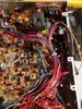
Post a picture of the board area you tested .
The voltage regulator is on the right side of the radio in the middle/front of the right side rail (that is, with the cover off and looking at the component side); not on the back/right side rail.
From front to back along the right side rail, it is the voltage reg, audio IC, and then the AM reg - in that order.
I think you tested the wrong part.
Post a picture of the board area you tested .
Last edited:
Here ya goAccording to Nomad's schematic, the onboard power supply uses a LM7809 voltage regulator. The part number that you posted is better described as the the AM Regulator. Test the voltage again; this time in AM, and USB or LSB. The voltage you posted sounds correct for the AM reg - depending in which mode it is in.
The voltage regulator is on the right side of the radio in the middle/front of the right side rail (that is, with the cover off and looking at the component side); not on the back/right side rail.
From front to back along the right side rail, it is the voltage reg, audio IC, and then the AM reg - in that order.
I think you tested the wrong part.
Post a picture of the board area you tested .
Attachments

OK; that is correct.
If you have a freq counter; then I suggest that you next check your freq's in loop osc circuit and see if they are correct in all modes.
If you have a freq counter; then I suggest that you next check your freq's in loop osc circuit and see if they are correct in all modes.
dxChat
- No one is chatting at the moment.
-
-
dxBot:63Sprint has left the room.
-
dxBot:kennyjames 0151 has left the room.
-
-